
Electrical equipment of the car engine Honda Civic 3 and 4

Engine Electrical System Specifications
Ignition coil Primary winding resistance: 1984 - 1.24-1.46 ohms 1985 - 1.06-1.24 ohms 1986 and 1987 (between terminals A and D) - 1.2-1.5 Ohm since 1988 (between terminals A and O) - 0.3-0.5 ohm Secondary winding...
Ignition coil Primary winding resistance: 1984 - 1.24-1.46 ohms 1985 - 1.06-1.24 ohms 1986 and 1987 (between terminals A and D) - 1.2-1.5 Ohm since 1988 (between terminals A and O) - 0.3-0.5 ohm Secondary winding...
General information about the electrical equipment of the engine
Engine electrical systems include ignition, charging and starting systems. The rest of the electrical equipment is described in Chapter 12 . Remember: A) be careful when servicing the electrical system; b) turn off the...
Engine electrical systems include ignition, charging and starting systems. The rest of the electrical equipment is described in Chapter 12 . Remember: A) be careful when servicing the electrical system; b) turn off the...
Emergency charging and start
See Start this guide.
See Start this guide.
Battery cables — inspection and replacement
1. Periodically inspect cables. Do not allow them to be damaged, insulation cracks and burnout. Poor cable contacts with the battery, housing and starter are one of the reasons for difficult starting of the engine. 2....
1. Periodically inspect cables. Do not allow them to be damaged, insulation cracks and burnout. Poor cable contacts with the battery, housing and starter are one of the reasons for difficult starting of the engine. 2....
Battery — removal and installation
1. Attention: always disconnect the negative cable first. 2. Release the battery holders. 3. Lift up the battery. 4. With the battery removed, inspect its installation area (tray) for corrosion. 5. If corrosion has...
1. Attention: always disconnect the negative cable first. 2. Release the battery holders. 3. Lift up the battery. 4. With the battery removed, inspect its installation area (tray) for corrosion. 5. If corrosion has...

Ignition system — general information
Attention: high voltage! Be careful when working with the ignition system. The electronic ignition system consists of a key, a battery, a coil, a distributor, high-voltage wires and spark plugs (see fig. 5.1). Pic. 5.1...
Attention: high voltage! Be careful when working with the ignition system. The electronic ignition system consists of a key, a battery, a coil, a distributor, high-voltage wires and spark plugs (see fig. 5.1). Pic. 5.1...
Ignition system — control
Attention: High voltage! 1. Turn the ignition key to the second position (the light should be on "battery" and/or "oil pressure"). Thus, you have turned on the power of the electronic module. 2. Check for visible damage...
Attention: High voltage! 1. Turn the ignition key to the second position (the light should be on "battery" and/or "oil pressure"). Thus, you have turned on the power of the electronic module. 2. Check for visible damage...

Ignition coil — control and replacement
Control 1. During this work, the ignition key must be in the second position. 2. Remove the rubber caps from the coil and disconnect the center wire. Tag and remove the remaining wires. Models 1984, 1985 3. Measure the...
Control 1. During this work, the ignition key must be in the second position. 2. Remove the rubber caps from the coil and disconnect the center wire. Tag and remove the remaining wires. Models 1984, 1985 3. Measure the...

Control and replacement of the ignition interrupter
Note: if your distributor looks like the one shown in fig. 8.7a is the TOYO DENSO distributor. Otherwise, HITACHI firms. 1. Remove the distributor cap ( see chapter 1 ). 2. Remove the breaker wires (see fig. 8.2). 3....
Note: if your distributor looks like the one shown in fig. 8.7a is the TOYO DENSO distributor. Otherwise, HITACHI firms. 1. Remove the distributor cap ( see chapter 1 ). 2. Remove the breaker wires (see fig. 8.2). 3....
RFI Capacitor — Inspection and Replacement
Note: a failed capacitor can cause the engine to shut down, so information on it is placed in this chapter. 1. Measure the capacitance of the capacitor and compare it with the specification data. 2. In the absence of a...
Note: a failed capacitor can cause the engine to shut down, so information on it is placed in this chapter. 1. Measure the capacitance of the capacitor and compare it with the specification data. 2. In the absence of a...

Ignition distributor — removal and installation
Withdrawal 1. Disconnect the negative cable from the battery. 2. Disconnect the regulator vacuum hose. 3. Disconnect the low voltage wires from the coil. 4. Determine the label position "1" on the cover corresponding to...
Withdrawal 1. Disconnect the negative cable from the battery. 2. Disconnect the regulator vacuum hose. 3. Disconnect the low voltage wires from the coil. 4. Determine the label position "1" on the cover corresponding to...

Magnetic resistance gap (1984-1987 models only) — control and adjustment
1. Disconnect the negative cable from the battery. 2. Remove the distributor cap and rotor ( see chapter 1 ). 3. Using non-magnetic feelers, check the equality of the air gap between the stator and the magnetic...
1. Disconnect the negative cable from the battery. 2. Remove the distributor cap and rotor ( see chapter 1 ). 3. Using non-magnetic feelers, check the equality of the air gap between the stator and the magnetic...

Magnetic resistance (1984-1987) — replacement
1. Disconnect the negative cable from the battery. 2. Remove the distributor cap. 3. Remove the magnetic resistance by prying it off with a pair of suitable screwdrivers. Be careful: too much force can damage the...
1. Disconnect the negative cable from the battery. 2. Remove the distributor cap. 3. Remove the magnetic resistance by prying it off with a pair of suitable screwdrivers. Be careful: too much force can damage the...

Vacuum Ignition Advance Controller — Inspection and Replacement
Control 1. Disconnect the negative cable from the battery. 2. Remove the distributor cap. 3. Disconnect vacuum hoses from a diaphragm of a vacuum regulator. Connect vacuum pump to diaphragm port (if there are two hoses,...
Control 1. Disconnect the negative cable from the battery. 2. Remove the distributor cap. 3. Disconnect vacuum hoses from a diaphragm of a vacuum regulator. Connect vacuum pump to diaphragm port (if there are two hoses,...
Centrifugal Ignition Advance Controller — Control
1. Disconnect the vacuum advance control hoses and plug them. 2. Connect the stoboscope according to the manufacturer's instructions. 3. Start the engine and increase the speed to 2500 rpm. In the viewing window between...
1. Disconnect the vacuum advance control hoses and plug them. 2. Connect the stoboscope according to the manufacturer's instructions. 3. Start the engine and increase the speed to 2500 rpm. In the viewing window between...
Charging system — general information
The charging system includes a generator, voltage regulator, charging indicator, battery, fuses and wires. The generator is driven by a belt from the engine shaft. The motor wiring includes short pieces of calibrated...
The charging system includes a generator, voltage regulator, charging indicator, battery, fuses and wires. The generator is driven by a belt from the engine shaft. The motor wiring includes short pieces of calibrated...
Charging system — control
1. Procedure for checking the system: A) check belt tension and condition ( see chapter 1 ) if necessary, replace the belt; b) check the tightening of the adjusting and fixing bolts of the generator; V) check the...
1. Procedure for checking the system: A) check belt tension and condition ( see chapter 1 ) if necessary, replace the belt; b) check the tightening of the adjusting and fixing bolts of the generator; V) check the...
Generator — removal and installation
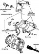
1. Disconnect the negative cable from the battery. 2. Tag and disconnect the wires from the generator. 3. Loosen the adjusting bolt and axle bolt nut, remove the belt. Pic. 17.3 Typical generator mounting 4. Remove a...
1. Disconnect the negative cable from the battery. 2. Tag and disconnect the wires from the generator. 3. Loosen the adjusting bolt and axle bolt nut, remove the belt. Pic. 17.3 Typical generator mounting 4. Remove a...

Voltage regulator and alternator brushes — replacement
1. Remove the generator ( see Section 17 ). 2. Remove the three rear cover nuts, nut and electrical contact insulator, and remove the rear cover. Pic. 18.2 Assembling the generator 1 - contact; 2 - back cover; 3 - brush...
1. Remove the generator ( see Section 17 ). 2. Remove the three rear cover nuts, nut and electrical contact insulator, and remove the rear cover. Pic. 18.2 Assembling the generator 1 - contact; 2 - back cover; 3 - brush...
Starting system — general information
The purpose of the system is to rotate the engine crankshaft at a frequency sufficient to start. The starting system consists of a battery, starter motor, starter relay and wires. The starter relay is attached directly...
The purpose of the system is to rotate the engine crankshaft at a frequency sufficient to start. The starting system consists of a battery, starter motor, starter relay and wires. The starter relay is attached directly...
Starter — control on the car
Note: Before diagnosing the starter, make sure the battery is fully charged. 1. If the starter does not rotate when the key is turned to the third position, make sure the gear lever is in the neutral position. 2. Check...
Note: Before diagnosing the starter, make sure the battery is fully charged. 1. If the starter does not rotate when the key is turned to the third position, make sure the gear lever is in the neutral position. 2. Check...
Starter — removal and installation
1. Disconnect the negative cable from the battery. 2. Tag and disconnect the wires from the starter. 3. Turn away bolts and remove a starter.
1. Disconnect the negative cable from the battery. 2. Tag and disconnect the wires from the starter. 3. Turn away bolts and remove a starter.
Starter solenoid — removal and installation
1. Disconnect the negative cable from the battery. 2. Remove the starter ( see Section 21 ). 3. Disconnect the thick wire from the solenoid. 4. Turn away bolts of fastening of the solenoid and remove it. 5. With the...
1. Disconnect the negative cable from the battery. 2. Remove the starter ( see Section 21 ). 3. Disconnect the thick wire from the solenoid. 4. Turn away bolts of fastening of the solenoid and remove it. 5. With the...
This section is available on: russian, bulgarian, belarusian, ukrainian, serbian, croatian, romanian, polish, slovak, hungarian
Link in different formats to this section
TEXTHTMLBB Code
- General information
- Technical data
- Governing bodies
- Driving and maintenance
- Power unit
- Gasoline engines (L13A)
- Gasoline engines (R18A)
- Diesel engines (N22A)
- Cooling and lubrication (L13A)
- Cooling and lubrication (R18A)
- Cooling and lubrication (N22A)
- Injection system (gasoline)
- Injection system (diesel)
- Toxicity reduction system
- Troubleshooting
- Transmission
- Clutch and drive shafts
- Mechanical gearbox
- Chassis and running gear
- Suspension and wheels
- Steering
- Brake system
- Body and interior
- Exterior (external elements)
- Doors, locks and windows
- Electrical equipment
- Equipment and devices
- Headlights and lighting
- Power devices
- Electrical circuits
- General information
- Introduction to guide
- User manual
- Maintenance
- Power unit
- Engine in car (Civic)
- Engine in car (Integra)
- Engine overhaul
- Cooling and heating
- Power and exhaust systems
- Engine electrical equipment
- Engine management systems
- Transmission
- Manual gearbox
- Automatic transmission (AT/CVT)
- Clutch and drive shafts
- Chassis and running gear
- Brake system
- Car suspension
- Steering
- Body and interior
- Exterior (external elements)
- Interior (internal elements)
- Doors, locks and windows
- Electrical equipment
- Equipment and devices
- Electrical circuits
- Power unit
- SOHC engines
- DOHC engines
- Engine overhaul
- Cooling and lubrication system
- Intake and exhaust system
- Fuel injection system (SOHC)
- Fuel injection system (DOHC)
- Carburetor
- Transmission
- Clutch
- Manual gearbox S4C
- Manual gearbox S40
- Automatic gearbox
- Drive shafts
- Chassis and running gear
- Car suspension
- Steering
- Brake system
- Body and interior
- Body elements
- Heater and air conditioner
- Electrical equipment
- Power devices
- Equipment and instruments
- Electrical circuits
- General information
- Maintenance
- Power unit
- Engine in a car
- Engine overhaul
- Cooling system
- Power and exhaust system
- Engine electrical equipment
- Emission control system
- Transmission
- Mechanical gearbox
- Automatic gearbox
- Clutch and drive shafts
- Four-wheel drive
- Chassis and running gear
- Brake system
- Car suspension
- Steering
- Body and interior
- Body elements
- Electrical equipment
- Equipment and devices
- Electrical circuits
HondaBook.ru © 2018–2024 • Mobile version • Sitemap: EN BG BY UA RS HR RO PL SK HU • Feedback • Driver Information • Search system • Bookmark
Accord 3 (1985-1989) • Accord 6 (1997-2002) • Civic 3 and 4 (1983-1991) • Civic 5 and 6 (1991-2000) • Civic 6 (1995-2000) • Civic 8 (2005-2011) • Fit 1 (2001-2008) • CR-V 1 (1995-2001) • HR-V 1 (1998-2006) • Avancier 1 (1999-2003) •
Accord 3 (1985-1989) • Accord 6 (1997-2002) • Civic 3 and 4 (1983-1991) • Civic 5 and 6 (1991-2000) • Civic 6 (1995-2000) • Civic 8 (2005-2011) • Fit 1 (2001-2008) • CR-V 1 (1995-2001) • HR-V 1 (1998-2006) • Avancier 1 (1999-2003) •