
Car heater and air conditioner Honda Civic 5 and 6

Heater — faults, control panel
Malfunctions Symptom chart Note: Check the engine coolant level and allow the engine to warm up before you begin troubleshooting. All problems must be corrected before testing. Since accurate measurements are necessary,...
Malfunctions Symptom chart Note: Check the engine coolant level and allow the engine to warm up before you begin troubleshooting. All problems must be corrected before testing. Since accurate measurements are necessary,...

Fan assembly
Replacement Note: LHD type shown, RHD type similar. The fan motor, recirculation control motor, and fan resistor can be replaced without removing the fan assembly. 1. Remove the glove box. 2. Remove the self-tapping...
Replacement Note: LHD type shown, RHD type similar. The fan motor, recirculation control motor, and fan resistor can be replaced without removing the fan assembly. 1. Remove the glove box. 2. Remove the self-tapping...

Heater assembly
Replacement SRS parts are located in this area. Review the SRS parts location, safety precautions, and work procedures in the SRS section before attempting any repairs or maintenance. Note: LHD type shown. RHD type is...
Replacement SRS parts are located in this area. Review the SRS parts location, safety precautions, and work procedures in the SRS section before attempting any repairs or maintenance. Note: LHD type shown. RHD type is...

Heating control panel
Replacement 1. Remove the driver's side lower instrument panel cover, glove box and lower center panel cover. 2. Disconnect the air flow control cable from the radiator assembly. 3. Remove the rear window defogger...
Replacement 1. Remove the driver's side lower instrument panel cover, glove box and lower center panel cover. 2. Disconnect the air flow control cable from the radiator assembly. 3. Remove the rear window defogger...

Heater control panel
Major renovation Replacing the air flow control cable Note: LHD type is shown, RHD type is similar. 1. Cut the inner cable from the cable release lever side, then remove both pieces of the inner cable. 2. Using a sharp...
Major renovation Replacing the air flow control cable Note: LHD type is shown, RHD type is similar. 1. Cut the inner cable from the cable release lever side, then remove both pieces of the inner cable. 2. Using a sharp...

Heater valve cable
Adjustment LHD type: 1. Disconnect the heater valve cable from the valve lever and clamp and from the heater control lever and clamp. 2. Set the temperature control lever to MAX. COOL 3. Rotate the heater control lever...
Adjustment LHD type: 1. Disconnect the heater valve cable from the valve lever and clamp and from the heater control lever and clamp. 2. Set the temperature control lever to MAX. COOL 3. Rotate the heater control lever...

Air flow control cable
Adjustment LHD type: 1. Disconnect the air control cable from the air control lever and clamp. 2. Set the temperature control lever to MAX. COOL. 3. Rotate the airflow control lever as shown, then connect the end of the...
Adjustment LHD type: 1. Disconnect the air control cable from the air control lever and clamp. 2. Set the temperature control lever to MAX. COOL. 3. Rotate the airflow control lever as shown, then connect the end of the...

Mode control engine
Examination 1. Disconnect the 7K connector from the mode control motor. 2. Connect the battery (+) to pin #1 and ground pin #7. Attention. Never connect the battery in the opposite direction. 3. Using a jumper wire,...
Examination 1. Disconnect the 7K connector from the mode control motor. 2. Connect the battery (+) to pin #1 and ground pin #7. Attention. Never connect the battery in the opposite direction. 3. Using a jumper wire,...

Recirculation control motor
Examination 1. Disconnect the 4K connector from the recirculation control motor. 2. Connect the battery (+) to pin No. 1 and ground pins No. 2 and No. 4, the recirculation control motor should run smoothly. Attention....
Examination 1. Disconnect the 4K connector from the recirculation control motor. 2. Connect the battery (+) to pin No. 1 and ground pins No. 2 and No. 4, the recirculation control motor should run smoothly. Attention....

Relay — check
There should be continuity between pins #1 and #3 when power and ground are connected to pins #2 and #4 and there should also be no continuity when power is disconnected.
There should be continuity between pins #1 and #3 when power and ground are connected to pins #2 and #4 and there should also be no continuity when power is disconnected.

Heater operating mode switch
Examination Check the continuity between terminals according to the table below.
Examination Check the continuity between terminals according to the table below.

Heater fan switch
Examination Check the continuity between the contacts according to the table below.
Examination Check the continuity between the contacts according to the table below.

Damper position switch
Examination Check the continuity between terminals according to the table below.
Examination Check the continuity between terminals according to the table below.

A/C filter
Replacement 1. Remove the filter cover and pull out the A/C filter. Replace the A/C filter every 30,000 km or 12 months, whichever comes first. 2. Install in the reverse order of removal. Make sure there is no air leak.
Replacement 1. Remove the filter cover and pull out the A/C filter. Replace the A/C filter every 30,000 km or 12 months, whichever comes first. 2. Install in the reverse order of removal. Make sure there is no air leak.

Air conditioning — description
Location of main elements Drawings shown are for left hand drive. Right-hand drive - symmetrical arrangement. Location of connectors and wiring harnesses Description Review The air conditioning system removes heat from...
Location of main elements Drawings shown are for left hand drive. Right-hand drive - symmetrical arrangement. Location of connectors and wiring harnesses Description Review The air conditioning system removes heat from...
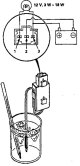
Thermostat A/C
Trial Attach (+) power supply to pin±3, ground pin±2 and connect a test light between pins±1 and±3. Note: Use a 12V, 3-18W light bulb. Immerse the A/C thermostat in a glass of ice water and check the control light. The...
Trial Attach (+) power supply to pin±3, ground pin±2 and connect a test light between pins±1 and±3. Note: Use a 12V, 3-18W light bulb. Immerse the A/C thermostat in a glass of ice water and check the control light. The...

A/C switch
Trial Check the continuity between the contacts according to the table below.
Trial Check the continuity between the contacts according to the table below.

Relay — test
There should be continuity between pins±1 and±3 when pins±2 and±4 are connected to power and chassis, and there should be no continuity when disconnected.
There should be continuity between pins±1 and±3 when pins±2 and±4 are connected to power and chassis, and there should be no continuity when disconnected.

A/C filter — replacement
Replacement 1. Remove the glove box and glove box frame. 2. Remove the evaporator cover and remove the A/C filter. Replace the A/C filter every 30,000 km or 12 months, whichever comes first. 3. Install the parts in the...
Replacement 1. Remove the glove box and glove box frame. 2. Remove the evaporator cover and remove the A/C filter. Replace the A/C filter every 30,000 km or 12 months, whichever comes first. 3. Install the parts in the...

Notes and cautions for servicing A/C
This A/C system uses HFC-134a refrigerant (R-134a) and refrigerant oil (PAG) stamps (Nippondenso: ND-OILB, P/N 39899-PR7 003 or P/N 38899-PR7-A01, or brand SP-10. P/N-38899-P13-003 or P/N 38899-P13-A01, designed for...
This A/C system uses HFC-134a refrigerant (R-134a) and refrigerant oil (PAG) stamps (Nippondenso: ND-OILB, P/N 39899-PR7 003 or P/N 38899-PR7-A01, or brand SP-10. P/N-38899-P13-003 or P/N 38899-P13-A01, designed for...

Evaporator — replacement, major repairs
Replacement Note: LHD type shown, RHD type is similar. 1. Remove the battery. 2. Release the refrigerant. 3. Remove the bolts and disconnect the lines from the evaporator. Note: Close the line openings immediately after...
Replacement Note: LHD type shown, RHD type is similar. 1. Remove the battery. 2. Release the refrigerant. 3. Remove the bolts and disconnect the lines from the evaporator. Note: Close the line openings immediately after...

Compressor (Nippondenso)
Replacement Note: LHD type shown, RHD type is similar. 1. If the compressor has operating capacity, start the engine at idle speed and let the air conditioner run for a few minutes, then turn off the engine. 2....
Replacement Note: LHD type shown, RHD type is similar. 1. If the compressor has operating capacity, start the engine at idle speed and let the air conditioner run for a few minutes, then turn off the engine. 2....

Compressor belt A/C
Adjustment Deflection method 1. Apply a force of 98 N (10 kgf), and measure the belt deflection between the compressor and crankshaft pulleys. Compressor belt A/C Used belt, engines V16A2, V16A4, V16A6: 6.0-9.5 mm...
Adjustment Deflection method 1. Apply a force of 98 N (10 kgf), and measure the belt deflection between the compressor and crankshaft pulleys. Compressor belt A/C Used belt, engines V16A2, V16A4, V16A6: 6.0-9.5 mm...

Charging the air conditioner
Note: Use only the sensor set for HFC-134a (R-134a). Use a vacuum pump adapter with a built-in one-way valve to prevent pump oil from entering the system. Warning When working with HFC-134a refrigerant (R-34a): Always...
Note: Use only the sensor set for HFC-134a (R-134a). Use a vacuum pump adapter with a built-in one-way valve to prevent pump oil from entering the system. Warning When working with HFC-134a refrigerant (R-34a): Always...

Leak check
Note: Use only the sensor set for HFC-134a (R-134a). Use a vacuum pump adapter with a built-in one-way valve to prevent pump oil from entering the system. Warning When working with HFC-134a refrigerant (R-134a): Always...
Note: Use only the sensor set for HFC-134a (R-134a). Use a vacuum pump adapter with a built-in one-way valve to prevent pump oil from entering the system. Warning When working with HFC-134a refrigerant (R-134a): Always...

Climate control system — malfunctions
Self-diagnosis function The microclimate control unit has a built-in self-diagnosis system. Self-diagnosis function operation Turn the ignition key to the ON position (II), press the AUTO and OFF buttons simultaneously....
Self-diagnosis function The microclimate control unit has a built-in self-diagnosis system. Self-diagnosis function operation Turn the ignition key to the ON position (II), press the AUTO and OFF buttons simultaneously....

Microclimate control unit
Replacement 1. Remove the driver's side lower instrument panel cover, glove box, and center lower instrument panel cover. 2. Remove the rear window heater switch. hazard warning switch and receiver/player. 3. Disconnect...
Replacement 1. Remove the driver's side lower instrument panel cover, glove box, and center lower instrument panel cover. 2. Remove the rear window heater switch. hazard warning switch and receiver/player. 3. Disconnect...

Internal temperature sensor
Replacement 1. Remove the driver's side lower dashboard cover, then disconnect the 2K connector of the internal temperature sensor and the air hose. 2. Remove the two self-tapping screws and the internal temperature...
Replacement 1. Remove the driver's side lower dashboard cover, then disconnect the 2K connector of the internal temperature sensor and the air hose. 2. Remove the two self-tapping screws and the internal temperature...

External temperature sensor
Replacement 1. Disconnect the 2K external temperature sensor. 2. Press the latch and remove the external temperature sensor. 3. The installation order is the reverse of the removal order. Trial Compare the resistance...
Replacement 1. Disconnect the 2K external temperature sensor. 2. Press the latch and remove the external temperature sensor. 3. The installation order is the reverse of the removal order. Trial Compare the resistance...

Sunlight sensor
Replacement 1. Remove the sunlight sensor from the dashboard and disconnect the 2K connector. Note: Be careful not to damage the panel. 2. The installation order is the reverse of the removal order. Trial Turn on the...
Replacement 1. Remove the sunlight sensor from the dashboard and disconnect the 2K connector. Note: Be careful not to damage the panel. 2. The installation order is the reverse of the removal order. Trial Turn on the...

Air mixture control motor
Replacement 1. Disconnect the 5K connector from the air mixture control motor. 2. Remove the three self-tapping screws, air control motor and flange bushing. 3. Install the parts in the reverse order of removal. After...
Replacement 1. Disconnect the 5K connector from the air mixture control motor. 2. Remove the three self-tapping screws, air control motor and flange bushing. 3. Install the parts in the reverse order of removal. After...
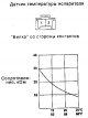
Evaporator temperature sensor
Trial Compare the resistance between contacts No. 1 and No. 2 of the sensor with that indicated on the graph, at the appropriate temperature. The resistance should be close to the specified value. Note: Immerse the...
Trial Compare the resistance between contacts No. 1 and No. 2 of the sensor with that indicated on the graph, at the appropriate temperature. The resistance should be close to the specified value. Note: Immerse the...
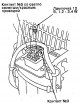
Power transistor
Trial 1. Disconnect the 5K power transistor connector. 2. Remove pin No. 5 with the light green/red wire from the connector, then connect a 1.2 - 3.4 W light bulb to sockets No. 3 and No. 5 of the connector as shown. 3....
Trial 1. Disconnect the 5K power transistor connector. 2. Remove pin No. 5 with the light green/red wire from the connector, then connect a 1.2 - 3.4 W light bulb to sockets No. 3 and No. 5 of the connector as shown. 3....
This section is available on: russian, bulgarian, belarusian, ukrainian, serbian, croatian, romanian, polish, slovak, hungarian
Link in different formats to this section
TEXTHTMLBB Code
- General information
- Technical data
- Governing bodies
- Driving and maintenance
- Power unit
- Gasoline engines (L13A)
- Gasoline engines (R18A)
- Diesel engines (N22A)
- Cooling and lubrication (L13A)
- Cooling and lubrication (R18A)
- Cooling and lubrication (N22A)
- Injection system (gasoline)
- Injection system (diesel)
- Toxicity reduction system
- Troubleshooting
- Transmission
- Clutch and drive shafts
- Mechanical gearbox
- Chassis and running gear
- Suspension and wheels
- Steering
- Brake system
- Body and interior
- Exterior (external elements)
- Doors, locks and windows
- Electrical equipment
- Equipment and devices
- Headlights and lighting
- Power devices
- Electrical circuits
- General information
- Introduction to guide
- User manual
- Maintenance
- Power unit
- Engine in car (Civic)
- Engine in car (Integra)
- Engine overhaul
- Cooling and heating
- Power and exhaust systems
- Engine electrical equipment
- Engine management systems
- Transmission
- Manual gearbox
- Automatic transmission (AT/CVT)
- Clutch and drive shafts
- Chassis and running gear
- Brake system
- Car suspension
- Steering
- Body and interior
- Exterior (external elements)
- Interior (internal elements)
- Doors, locks and windows
- Electrical equipment
- Equipment and devices
- Electrical circuits
- Power unit
- SOHC engines
- DOHC engines
- Engine overhaul
- Cooling and lubrication system
- Intake and exhaust system
- Fuel injection system (SOHC)
- Fuel injection system (DOHC)
- Carburetor
- Transmission
- Clutch
- Manual gearbox S4C
- Manual gearbox S40
- Automatic gearbox
- Drive shafts
- Chassis and running gear
- Car suspension
- Steering
- Brake system
- Body and interior
- Body elements
- Heater and air conditioner
- Electrical equipment
- Power devices
- Equipment and instruments
- Electrical circuits
- General information
- Maintenance
- Power unit
- Engine in a car
- Engine overhaul
- Cooling system
- Power and exhaust system
- Engine electrical equipment
- Emission control system
- Transmission
- Mechanical gearbox
- Automatic gearbox
- Clutch and drive shafts
- Four-wheel drive
- Chassis and running gear
- Brake system
- Car suspension
- Steering
- Body and interior
- Body elements
- Electrical equipment
- Equipment and devices
- Electrical circuits
HondaBook.ru © 2018–2024 • Mobile version • Sitemap: EN BG BY UA RS HR RO PL SK HU • Feedback • Driver Information • Search system • Bookmark
Accord 3 (1985-1989) • Accord 6 (1997-2002) • Civic 3 and 4 (1983-1991) • Civic 5 and 6 (1991-2000) • Civic 6 (1995-2000) • Civic 8 (2005-2011) • Fit 1 (2001-2008) • CR-V 1 (1995-2001) • HR-V 1 (1998-2006) • Avancier 1 (1999-2003) •
Accord 3 (1985-1989) • Accord 6 (1997-2002) • Civic 3 and 4 (1983-1991) • Civic 5 and 6 (1991-2000) • Civic 6 (1995-2000) • Civic 8 (2005-2011) • Fit 1 (2001-2008) • CR-V 1 (1995-2001) • HR-V 1 (1998-2006) • Avancier 1 (1999-2003) •