
2. Unscrew the three nuts securing the back cover, the nut and the electrical contact insulator and remove the back cover.
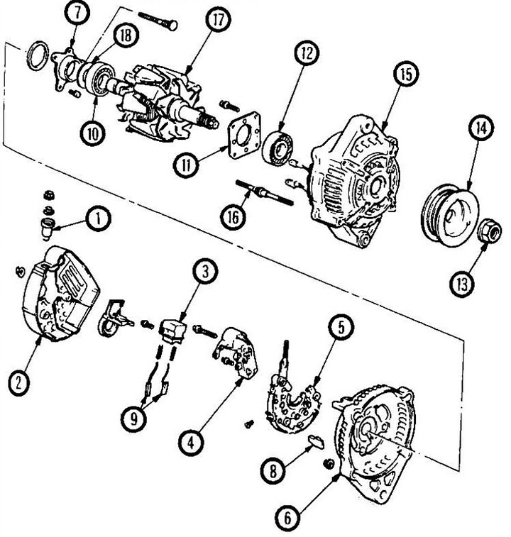
Fig. 18.2 Generator assembly 1 - contact; 2 - back cover; 3 - brush holder; 4 - regulator; 5 - rectifier; 6 - rear housing; 7 - bearing housing; 8 - insulator; 9 - brushes; 10 - rear bearing; 11 - bearing holder; 12 - front bearing; 13 - pulley nut; 14 - pulley; 15 - stator housing; 16 - tie bolt; 17 - rotor; 18 - spacer.
3. Unscrew the five bolts securing the regulator and brush holder.
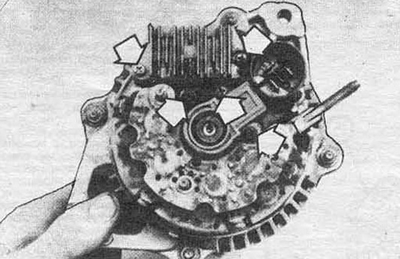
Fig. 18.3. Screws for fastening the regulator and brush holder
4. Remove the brush holder and regulator.
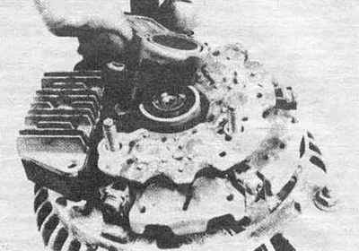
Fig. 18.4 Remove the brush holder, then the regulator
If you are replacing the regulator, go to step 8, if the brushes, go to step 5.
5. Measure the length of the brushes and compare it with the minimum allowable length. If it is less than the tolerance, replace the brushes.
6. Check the smooth movement of the brushes in the holder.
7. Install the holder by pressing on the brushes with a small screwdriver.
8. Install the screws securing the regulator and holder.
9. Install the back cover and tighten the nuts securely.
10. Assemble electrical contact B.
11. Install the generator on the engine (see Section 17).