
Electrical equipment of the car engine Honda CR-V 1

Distributor Ignition System — General Information
The CR-V and 4-cylinder Odyssey models use a contactless distributor ignition system. The ignition timing is controlled by the engine processor unit, which generates ignition control pulses in response to signals from 3...
The CR-V and 4-cylinder Odyssey models use a contactless distributor ignition system. The ignition timing is controlled by the engine processor unit, which generates ignition control pulses in response to signals from 3...

Checking the ignition system
Preliminary check the condition of the battery, fuses, corrosion on electrical connections, damage to insulation, reliability of the connector on the ignition module, condition of high-voltage wires and spark plugs,...
Preliminary check the condition of the battery, fuses, corrosion on electrical connections, damage to insulation, reliability of the connector on the ignition module, condition of high-voltage wires and spark plugs,...

Ignition Coil — Checking and Replacing
Examination 1. Disconnect the battery from ground and remove the distributor cap and gasket. 2. On some vehicles, loosen the locking screw, remove the runner and dust cover. 3. Check the resistance of the primary...
Examination 1. Disconnect the battery from ground and remove the distributor cap and gasket. 2. On some vehicles, loosen the locking screw, remove the runner and dust cover. 3. Check the resistance of the primary...

Electronic Ignition Module — Checking and Replacing
The module is mounted in the distributor housing next to the coil. To access it, remove the distributor cap, rotor and dust cover (on car parts). Examination Before removing, mark all wires on the module. CR-V Models 1....
The module is mounted in the distributor housing next to the coil. To access it, remove the distributor cap, rotor and dust cover (on car parts). Examination Before removing, mark all wires on the module. CR-V Models 1....

Ignition distributor — removal and installation
Removal 1. Disconnect the battery from ground. 2. After turning the crankshaft, align the white mark on the crankshaft pulley with the pointer on the front cover. 3. Mark the high voltage wires on the cover, do not...
Removal 1. Disconnect the battery from ground. 2. After turning the crankshaft, align the white mark on the crankshaft pulley with the pointer on the front cover. 3. Mark the high voltage wires on the cover, do not...

Ignition system without distributor
General information The V6 Odyssey models are equipped with a distributorless ignition system. The ignition timing is adjusted automatically by the engine's PCM processor unit (Powertrain Control Module). In this...
General information The V6 Odyssey models are equipped with a distributorless ignition system. The ignition timing is adjusted automatically by the engine's PCM processor unit (Powertrain Control Module). In this...

Ignition Coil Pack — Checking and Replacing
Examination 1. Remove the ignition coil cover. 2. Label and disconnect the connectors from all 6 coils. 3. Turn on the ignition and check the voltage at the black/yellow wire of each connector. If there is no voltage,...
Examination 1. Remove the ignition coil cover. 2. Label and disconnect the connectors from all 6 coils. 3. Turn on the ignition and check the voltage at the black/yellow wire of each connector. If there is no voltage,...

Engine operating order
In order not to disrupt the engine's operating order, the ignition distributor should be installed so that the protrusions on the distributor tailpiece fit into the grooves on the camshaft and the wires should be...
In order not to disrupt the engine's operating order, the ignition distributor should be installed so that the protrusions on the distributor tailpiece fit into the grooves on the camshaft and the wires should be...
Battery Charging System — General Information
The charging system of the vehicles under consideration consists of a generator, a voltage regulator built into the generator, a battery, a charge control circuit, connecting wires, a fuse box with a built-in load...
The charging system of the vehicles under consideration consists of a generator, a voltage regulator built into the generator, a battery, a charge control circuit, connecting wires, a fuse box with a built-in load...

Checking the generator
To access the generator terminals for inspection, you must remove the air filter or raise the vehicle. Generator Voltage Drop Test 1. The test is performed on a warm engine. 2. Connect the tachometer, start the engine...
To access the generator terminals for inspection, you must remove the air filter or raise the vehicle. Generator Voltage Drop Test 1. The test is performed on a warm engine. 2. Connect the tachometer, start the engine...
Removal and installation the generator
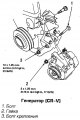
CR-V 1. Disconnect the battery from ground. 2. Disconnect the fork connector from the generator and the white wire on the rear cover 3. Loosen the adjusting bolt nut and remove the belt. 4. Remove the through bolt and...
CR-V 1. Disconnect the battery from ground. 2. Disconnect the fork connector from the generator and the white wire on the rear cover 3. Loosen the adjusting bolt nut and remove the belt. 4. Remove the through bolt and...

Checking the starter
The starting system consists of a battery, starter, traction relay, ignition switch and connecting wires. When the crankshaft rotates, the starter should consume a current of 250 A, and the voltage on the battery should...
The starting system consists of a battery, starter, traction relay, ignition switch and connecting wires. When the crankshaft rotates, the starter should consume a current of 250 A, and the voltage on the battery should...

Traction relay — checking and replacement
When the engine starts, there should be battery voltage between the S terminal of the relay and ground. Replace the relay that has no winding circuit to ground, or has an open winding. Removal and installation 1. On V6...
When the engine starts, there should be battery voltage between the S terminal of the relay and ground. Replace the relay that has no winding circuit to ground, or has an open winding. Removal and installation 1. On V6...

Removal and installation the starter
Starter mounting bolts (CR-V): 1. Terminal nut B; 2. Wire Starter (Odyssey 1995-98): 1, 4. Bolt; 2. Wire; 3. Conclusion S; 5. Conclusion B; 6. Nut Starter mounting bolts (Odyssey 1999-00)
Starter mounting bolts (CR-V): 1. Terminal nut B; 2. Wire Starter (Odyssey 1995-98): 1, 4. Bolt; 2. Wire; 3. Conclusion S; 5. Conclusion B; 6. Nut Starter mounting bolts (Odyssey 1999-00)

Coolant temperature sensor
The sensor resistance should be 137 Ohm at 56°C and 36-46 Ohm at 85-100°C. To remove the sensor, drain the fluid and unscrew the sensor. Checking the Coolant Temperature Sensor (CR-V) Checking the coolant temperature...
The sensor resistance should be 137 Ohm at 56°C and 36-46 Ohm at 85-100°C. To remove the sensor, drain the fluid and unscrew the sensor. Checking the Coolant Temperature Sensor (CR-V) Checking the coolant temperature...
Oil pressure sensor — check
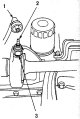
If the oil pressure warning light on a running engine does not go out, first check for a short circuit in the wire to ground. If the wire is in good condition, replace the sensor with a known good one. If the lamp still...
If the oil pressure warning light on a running engine does not go out, first check for a short circuit in the wire to ground. If the wire is in good condition, replace the sensor with a known good one. If the lamp still...

Fan switch sensor — check
CR-V 1. The sensor is mounted next to the thermostat and ignition distributor. 2. The sensor contacts should close at a temperature of 91-95°C and open at a temperature 3-8°C below the contact closing temperature....
CR-V 1. The sensor is mounted next to the thermostat and ignition distributor. 2. The sensor contacts should close at a temperature of 91-95°C and open at a temperature 3-8°C below the contact closing temperature....


Generator malfunctions and their possible causes
Typical faults indicated by the charge indicator lamp Generator malfunctions and their possible causes
Typical faults indicated by the charge indicator lamp Generator malfunctions and their possible causes

This section is available on: russian, bulgarian, belarusian, ukrainian, serbian, croatian, romanian, polish, slovak, hungarian
Link in different formats to this section
TEXTHTMLBB Code
- General information
- User manual
- Technical data
- Maintenance
- Power unit
- Engine repair
- Lubrication system
- Cooling system
- Exhaust system
- Fuel system
- Engine management
- Engine electrical equipment
- Transmission
- Clutch
- Manual gearbox
- Automatic gearbox
- Rear differential
- Drive shafts
- Chassis and running gear
- Steering
- Front suspension
- Rear suspension
- Brake system
- Body and interior
- Exterior (external elements)
- Interior (internal elements)
- Doors, locks and windows
- General information
- Maintenance
- Tips for car owner
- Power unit
- Engine repair
- Engine overhaul
- Cooling and lubrication system
- Engine electrical equipment
- Control system
- Fuel system
- Transmission
- Clutch and drive shafts
- Car gearbox
- Chassis and running gear
- Front suspension
- Rear suspension
- Steering
- Brake system
- Body and interior
- Body service
- Exterior (external elements)
- Interior (internal elements)
- Electrical equipment
- Equipment and devices
- Electrical circuits