
Car diesel engine injection system Honda Civic 8

Catalytic converter (N22A)
The machine combines two types of catalysts that differ in their cleaning principle: one performs both low-temperature oxidation and nitrogen oxide cleaning, while the other primarily cleans nitrogen oxides.
The machine combines two types of catalysts that differ in their cleaning principle: one performs both low-temperature oxidation and nitrogen oxide cleaning, while the other primarily cleans nitrogen oxides.

Diesel engine fuel supply system
Fuel coming from the tank is compressed by the fuel pump and accumulates in the common rail. The injection timing and amount of fuel injected is controlled by the ECM, which sends a signal to the solenoid valve of each...
Fuel coming from the tank is compressed by the fuel pump and accumulates in the common rail. The injection timing and amount of fuel injected is controlled by the ECM, which sends a signal to the solenoid valve of each...

Bleeding the fuel system (N22A)
Note: Air must be bled from the fuel after disassembling the fuel system for maintenance, or after the tank runs out of fuel. For information on how to perform this procedure, see here. 1. Fill the tank with fuel. 2....
Note: Air must be bled from the fuel after disassembling the fuel system for maintenance, or after the tank runs out of fuel. For information on how to perform this procedure, see here. 1. Fill the tank with fuel. 2....

Checking the suction pipe and fuel vent line (N22A)
1. Remove access panel A from the floor. 2. Disconnect the suction hose A from the fuel pump and connect the vacuum pump B. 3. Start the engine and check the vacuum hoses and tubes. If there is a vacuum, proceed to step...
1. Remove access panel A from the floor. 2. Disconnect the suction hose A from the fuel pump and connect the vacuum pump B. 3. Start the engine and check the vacuum hoses and tubes. If there is a vacuum, proceed to step...

Water bleeding of fuel filter (N22A)
1. Remove the air cleaner housing. 2. Place a container large enough to catch all the water under the fuel filter. 3. Connect the hose to the water tank cap B. 4. Unscrew the water tank cap and drain the water from the...
1. Remove the air cleaner housing. 2. Place a container large enough to catch all the water under the fuel filter. 3. Connect the hose to the water tank cap B. 4. Unscrew the water tank cap and drain the water from the...
Removal/installing fuel filter (N22A)
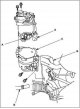
1. Remove the air cleaner housing. 2. Disconnect connectors A. 3. Disconnect hoses B. 4. Remove the fuel filter cover C. 5. Fix the fuel filter A in a vice. Insert the fuel filter wrench. 6. Remove the water level...
1. Remove the air cleaner housing. 2. Disconnect connectors A. 3. Disconnect hoses B. 4. Remove the fuel filter cover C. 5. Fix the fuel filter A in a vice. Insert the fuel filter wrench. 6. Remove the water level...

Checking the fuel level indicator sending device (N22A)
Note: To view the electrical diagram of the fuel level sensor, see the electrical diagram of the measuring instruments. 1. Check the integrity of the #10 (7.5 A) METER electrical fuse in the under-dash electrical...
Note: To view the electrical diagram of the fuel level sensor, see the electrical diagram of the measuring instruments. 1. Check the integrity of the #10 (7.5 A) METER electrical fuse in the under-dash electrical...

Replacing the fuel level indicator sending unit (N22A)
1. Remove the fuel tank filler cap. 2. Raise the center console and remove the parking brake lever A. 3. Remove access panel A from the floor. 4. Disconnect connector B from the fuel tank. 5. Disconnect the C line...
1. Remove the fuel tank filler cap. 2. Raise the center console and remove the parking brake lever A. 3. Remove access panel A from the floor. 4. Disconnect connector B from the fuel tank. 5. Disconnect the C line...
Checking the water level sensor in the fuel filter (N22A)
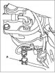
1. Perform the instrument control circuit test procedure. If the fuel gauge moves quickly from the minimum position to the maximum position and then returns to the minimum position again, the gauge is working properly....
1. Perform the instrument control circuit test procedure. If the fuel gauge moves quickly from the minimum position to the maximum position and then returns to the minimum position again, the gauge is working properly....

Replacing the water level sensor in the fuel filter (N22A)
1. Remove the fuel filter. 2. Secure fuel filter A in a vice. 3. Remove the water level indicator in the fuel filter B. 4. Install the part in the reverse order of removal, using a new sealing ring C. 5. Bleed the fuel...
1. Remove the fuel filter. 2. Secure fuel filter A in a vice. 3. Remove the water level indicator in the fuel filter B. 4. Install the part in the reverse order of removal, using a new sealing ring C. 5. Bleed the fuel...
Replacing the fuel pump (N22A)
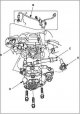
Removal 1. Remove the engine cover. 2. Remove the air cleaner housing. 3. Disconnect fuel pump connector A. 4. Remove high pressure pipe B. 5. Disconnect fuel hoses C. 6. Remove fuel pump D. Installation 1. Hand tighten...
Removal 1. Remove the engine cover. 2. Remove the air cleaner housing. 3. Disconnect fuel pump connector A. 4. Remove high pressure pipe B. 5. Disconnect fuel hoses C. 6. Remove fuel pump D. Installation 1. Hand tighten...

Replacing the fuel distribution system (N22A)
Removal 1. Remove the engine cover. 2. Remove the shield and the panel under the shield. 3. Disconnect FRP sensor connector A, IMRC solenoid valve connector B, fuel injector connectors C and glow plug connectors D. 4....
Removal 1. Remove the engine cover. 2. Remove the shield and the panel under the shield. 3. Disconnect FRP sensor connector A, IMRC solenoid valve connector B, fuel injector connectors C and glow plug connectors D. 4....

Replacing the fuel tank (N22A)
1. Empty the fuel tank, then disconnect the quick connectors B of the 4P connector A of the fuel tank unit A and the hose C. 2. Raise the car with a jack and place jack stands underneath it. 3. Remove the cover D and...
1. Empty the fuel tank, then disconnect the quick connectors B of the 4P connector A of the fuel tank unit A and the hose C. 2. Raise the car with a jack and place jack stands underneath it. 3. Remove the cover D and...

Replacing the fuel temperature sensor (N22A)
1. Remove the air cleaner housing. 2. Disconnect the 2-pin connector A of the fuel temperature sensor. 3. Remove fuel temperature sensor B. 4. Install the part in the reverse order of removal, using a new sealing ring...
1. Remove the air cleaner housing. 2. Disconnect the 2-pin connector A of the fuel temperature sensor. 3. Remove fuel temperature sensor B. 4. Install the part in the reverse order of removal, using a new sealing ring...

Checking the vacuum pump (N22A)
Note. During this check, diagnostic trouble codes may appear on the screen. When the test is complete, delete the fault codes using HDS. 1. Remove the engine cover. 2. Remove the shield and the panel under the shield....
Note. During this check, diagnostic trouble codes may appear on the screen. When the test is complete, delete the fault codes using HDS. 1. Remove the engine cover. 2. Remove the shield and the panel under the shield....

Replacing the vacuum pump (N22A)
1. Remove the intermediate shaft. 2. Remove the oil bypass tube. 3. Remove the timing chain housing and timing chain. 4. Disconnect the vacuum hose. 5. Remove bolts A. 6. Remove vacuum pump B. 7. Install the sensor in...
1. Remove the intermediate shaft. 2. Remove the oil bypass tube. 3. Remove the timing chain housing and timing chain. 4. Disconnect the vacuum hose. 5. Remove bolts A. 6. Remove vacuum pump B. 7. Install the sensor in...
This section is available on: russian, bulgarian, belarusian, ukrainian, serbian, croatian, romanian, polish, slovak, hungarian
Link in different formats to this section
TEXTHTMLBB Code
- General information
- Technical data
- Governing bodies
- Driving and maintenance
- Power unit
- Gasoline engines (L13A)
- Gasoline engines (R18A)
- Diesel engines (N22A)
- Cooling and lubrication (L13A)
- Cooling and lubrication (R18A)
- Cooling and lubrication (N22A)
- Injection system (gasoline)
- Injection system (diesel)
- Toxicity reduction system
- Troubleshooting
- Transmission
- Clutch and drive shafts
- Mechanical gearbox
- Chassis and running gear
- Suspension and wheels
- Steering
- Brake system
- Body and interior
- Exterior (external elements)
- Doors, locks and windows
- Electrical equipment
- Equipment and devices
- Headlights and lighting
- Power devices
- Electrical circuits
- General information
- User manual
- Maintenance
- Power unit
- Engines D15B and D17A
- K20A Engines
- Overhaul engine
- Cooling system
- Lubrication system
- Fuel injection system
- Toxicity reduction system
- Engine electrical equipment
- Transmission
- Clutch
- Manual gearbox
- Automatic gearbox
- Variator (CVT)
- Drive shafts
- Chassis and running gear
- Car suspension
- Steering
- Brake system
- Body and interior
- Exterior (external elements)
- Interior (internal elements)
- Doors, locks and windows
- Heater and air conditioner
- Manual air conditioner
- Automatic air conditioner
- Security system
- Electrical equipment
- Equipment and devices
- Headlights and lighting
- Windscreen wipers
- Audio system
- Electrical diagrams
- General information
- Introduction to guide
- User manual
- Maintenance
- Power unit
- Engine in car (Civic)
- Engine in car (Integra)
- Engine overhaul
- Cooling and heating
- Power and exhaust systems
- Engine electrical equipment
- Engine management systems
- Transmission
- Manual gearbox
- Automatic transmission (AT/CVT)
- Clutch and drive shafts
- Chassis and running gear
- Brake system
- Car suspension
- Steering
- Body and interior
- Exterior (external elements)
- Interior (internal elements)
- Doors, locks and windows
- Electrical equipment
- Equipment and devices
- Electrical circuits
- Power unit
- SOHC engines
- DOHC engines
- Engine overhaul
- Cooling and lubrication system
- Intake and exhaust system
- Fuel injection system (SOHC)
- Fuel injection system (DOHC)
- Carburetor
- Transmission
- Clutch
- Manual gearbox S4C
- Manual gearbox S40
- Automatic gearbox
- Drive shafts
- Chassis and running gear
- Car suspension
- Steering
- Brake system
- Body and interior
- Body elements
- Heater and air conditioner
- Electrical equipment
- Power devices
- Equipment and instruments
- Electrical circuits
- General information
- Maintenance
- Power unit
- Engine in a car
- Engine overhaul
- Cooling system
- Power and exhaust system
- Engine electrical equipment
- Emission control system
- Transmission
- Mechanical gearbox
- Automatic gearbox
- Clutch and drive shafts
- Four-wheel drive
- Chassis and running gear
- Brake system
- Car suspension
- Steering
- Body and interior
- Body elements
- Electrical equipment
- Equipment and devices
- Electrical circuits