
Petrol engine injection system Honda Civic 8

Fuel injection system components
Three-way catalytic converter (TWC) The three-way catalytic converter converts hydrocarbons (HC), carbon monoxide (CO) and nitrogen oxides (NOx) contained in the exhaust gases into carbon dioxide (CO ₂), nitrogen (N₂),...
Three-way catalytic converter (TWC) The three-way catalytic converter converts hydrocarbons (HC), carbon monoxide (CO) and nitrogen oxides (NOx) contained in the exhaust gases into carbon dioxide (CO ₂), nitrogen (N₂),...

PGM-FI fuel system
The Programmed Multi-Point Fuel Injection (PGM-FI) system is a sequential, multi-point fuel injection system. Air Conditioner (A/C) Clutch Relay When the ECM receives a command to turn on the air conditioner, it delays...
The Programmed Multi-Point Fuel Injection (PGM-FI) system is a sequential, multi-point fuel injection system. Air Conditioner (A/C) Clutch Relay When the ECM receives a command to turn on the air conditioner, it delays...

I-DSI fuel system
The ECM controls the timing of ignition timing between the front and rear spark plugs based on engine speed and intake manifold vacuum. At idle, the front and rear spark plugs fire simultaneously to increase combustion...
The ECM controls the timing of ignition timing between the front and rear spark plugs based on engine speed and intake manifold vacuum. At idle, the front and rear spark plugs fire simultaneously to increase combustion...

Electronic throttle control system
The throttle valve is electronically controlled by the electronic throttle position control system. See the system diagram for a functional diagram of this system. Idle mode control When the engine is idling, the ECM...
The throttle valve is electronically controlled by the electronic throttle position control system. See the system diagram for a functional diagram of this system. Idle mode control When the engine is idling, the ECM...
Removal/Installing Accelerator Pedal Module (L13A)
1. Disconnect the accelerator pedal module A connector. 2. Using a flat-blade screwdriver A, push the retaining plate B, then remove the accelerator pedal module C. Note: The APP sensor is not supplied as a spare part....
1. Disconnect the accelerator pedal module A connector. 2. Using a flat-blade screwdriver A, push the retaining plate B, then remove the accelerator pedal module C. Note: The APP sensor is not supplied as a spare part....
Checking the APP sensor signal (L13A)
Note: This procedure tests the APP sensor in its fully closed position. In any other position, the APP sensor stores DTCs that are covered in another troubleshooting procedure. Before performing this procedure, check...
Note: This procedure tests the APP sensor in its fully closed position. In any other position, the APP sensor stores DTCs that are covered in another troubleshooting procedure. Before performing this procedure, check...
Fuel supply system
Fuel Interruption Control When the vehicle is decelerating with the throttle valve closed, the electrical current to the injectors is interrupted to improve fuel economy at engine speeds above 900 rpm (min⁻¹) under no...
Fuel Interruption Control When the vehicle is decelerating with the throttle valve closed, the electrical current to the injectors is interrupted to improve fuel economy at engine speeds above 900 rpm (min⁻¹) under no...

Checking fuel pressure (L13A)
1. Relieve fuel pressure. 2. Disconnect quick release fastener A on fuel rail B. 3. Connect the fuel hose mounting device assembly E and the quick release fitting. Connect the fuel pressure gauge connection kit and the...
1. Relieve fuel pressure. 2. Disconnect quick release fastener A on fuel rail B. 3. Connect the fuel hose mounting device assembly E and the quick release fitting. Connect the fuel pressure gauge connection kit and the...

Checking the suction pipe and fuel vent line (L13A)
1. Remove access panel A from the floor. 2. Disconnect the suction hose A from the fuel pump and connect the vacuum pump B. 3. Start the engine and check the vacuum hoses and tubes. If there is a vacuum, proceed to step...
1. Remove access panel A from the floor. 2. Disconnect the suction hose A from the fuel pump and connect the vacuum pump B. 3. Start the engine and check the vacuum hoses and tubes. If there is a vacuum, proceed to step...

Replacing the fuel filter (L13A)
If the fuel pressure has dropped below the required value, the fuel filter must be replaced, after making sure that the fuel pump and fuel pressure regulator are in order. 1. Remove the fuel tank block. 2. Remove fuel...
If the fuel pressure has dropped below the required value, the fuel filter must be replaced, after making sure that the fuel pump and fuel pressure regulator are in order. 1. Remove the fuel tank block. 2. Remove fuel...
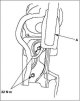
Checking the fuel level indicator transmitter (L13A)
Note: To view the electrical diagram of the fuel level sensor, see the electrical diagram of the measuring instruments. 1. Check the integrity of the #10 (7.5 A) METER electrical fuse in the under-dash electrical...
Note: To view the electrical diagram of the fuel level sensor, see the electrical diagram of the measuring instruments. 1. Check the integrity of the #10 (7.5 A) METER electrical fuse in the under-dash electrical...
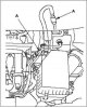
Removal the fuel line connectors of the fuel system (L13A)
Note: Read "Precautions for Fuel System Fuel Line Quick Connectors" before working on fuel lines and connections. 1. Relieve fuel pressure. 2. Check for dirt on the fuel line quick-release connector A and clean it if...
Note: Read "Precautions for Fuel System Fuel Line Quick Connectors" before working on fuel lines and connections. 1. Relieve fuel pressure. 2. Check for dirt on the fuel line quick-release connector A and clean it if...

Installation of fuel line connectors for the fuel system (L13A)
Note: Read "Precautions for Fuel System Fuel Line Quick Connectors" before working on fuel lines and connections. 1. Check the connection area A of pipe B to ensure there is no dirt or damage, and clean it if necessary....
Note: Read "Precautions for Fuel System Fuel Line Quick Connectors" before working on fuel lines and connections. 1. Check the connection area A of pipe B to ensure there is no dirt or damage, and clean it if necessary....

Replacing the fuel pressure regulator (L13A)
1. Remove the fuel tank block. 2. Remove clamps A and remove fuel pressure regulator B. 3. Install the part with new sealing rings C in the reverse order of removal. When installing the fuel pump/fuel level gauge...
1. Remove the fuel tank block. 2. Remove clamps A and remove fuel pressure regulator B. 3. Install the part with new sealing rings C in the reverse order of removal. When installing the fuel pump/fuel level gauge...
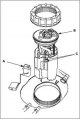
Replacing the fuel level indicator transmitter (L13A)
1. Remove the fuel tank block. 2. Disconnect the fuel level sensor (fuel level meter transmitting unit) And from the fuel pump/fuel level meter unit B. 3. Check the following points before installing the fuel pump/fuel...
1. Remove the fuel tank block. 2. Disconnect the fuel level sensor (fuel level meter transmitting unit) And from the fuel pump/fuel level meter unit B. 3. Check the following points before installing the fuel pump/fuel...

Troubleshooting the Fuel Pump Circuit (L13A)
Note: If you suspect any fault with the fuel pump, first make sure that it is working. To do this, remove the fuel filler cap and listen: if the pump is working, you will hear a characteristic sound. The fuel pump...
Note: If you suspect any fault with the fuel pump, first make sure that it is working. To do this, remove the fuel filler cap and listen: if the pump is working, you will hear a characteristic sound. The fuel pump...

Removal and installation the fuel tank (L13A)
Removal 1. Relieve fuel pressure. 2. Remove the center console and parking brake lever A. 3. Remove access panel A from the floor. 4. Disconnect the 4P connector B of the fuel pump. 5. Disconnect quick release fittings...
Removal 1. Relieve fuel pressure. 2. Remove the center console and parking brake lever A. 3. Remove access panel A from the floor. 4. Disconnect the 4P connector B of the fuel pump. 5. Disconnect quick release fittings...

Replacing the inertia switch (L13A)
1. Remove the lower instrument panel cover on the driver's side. 2. Disconnect the 3-pin (3P) connector A of the inertia switch. 3. Remove inertia switch B. 4. Install the parts in the reverse order of removal.
1. Remove the lower instrument panel cover on the driver's side. 2. Disconnect the 3-pin (3P) connector A of the inertia switch. 3. Remove inertia switch B. 4. Install the parts in the reverse order of removal.
This section is available on: russian, bulgarian, belarusian, ukrainian, serbian, croatian, romanian, polish, slovak, hungarian
Link in different formats to this section
TEXTHTMLBB Code
- General information
- Technical data
- Governing bodies
- Driving and maintenance
- Power unit
- Gasoline engines (L13A)
- Gasoline engines (R18A)
- Diesel engines (N22A)
- Cooling and lubrication (L13A)
- Cooling and lubrication (R18A)
- Cooling and lubrication (N22A)
- Injection system (gasoline)
- Injection system (diesel)
- Toxicity reduction system
- Troubleshooting
- Transmission
- Clutch and drive shafts
- Mechanical gearbox
- Chassis and running gear
- Suspension and wheels
- Steering
- Brake system
- Body and interior
- Exterior (external elements)
- Doors, locks and windows
- Electrical equipment
- Equipment and devices
- Headlights and lighting
- Power devices
- Electrical circuits
- General information
- User manual
- Maintenance
- Power unit
- Engines D15B and D17A
- K20A Engines
- Overhaul engine
- Cooling system
- Lubrication system
- Fuel injection system
- Toxicity reduction system
- Engine electrical equipment
- Transmission
- Clutch
- Manual gearbox
- Automatic gearbox
- Variator (CVT)
- Drive shafts
- Chassis and running gear
- Car suspension
- Steering
- Brake system
- Body and interior
- Exterior (external elements)
- Interior (internal elements)
- Doors, locks and windows
- Heater and air conditioner
- Manual air conditioner
- Automatic air conditioner
- Security system
- Electrical equipment
- Equipment and devices
- Headlights and lighting
- Windscreen wipers
- Audio system
- Electrical diagrams
- General information
- Introduction to guide
- User manual
- Maintenance
- Power unit
- Engine in car (Civic)
- Engine in car (Integra)
- Engine overhaul
- Cooling and heating
- Power and exhaust systems
- Engine electrical equipment
- Engine management systems
- Transmission
- Manual gearbox
- Automatic transmission (AT/CVT)
- Clutch and drive shafts
- Chassis and running gear
- Brake system
- Car suspension
- Steering
- Body and interior
- Exterior (external elements)
- Interior (internal elements)
- Doors, locks and windows
- Electrical equipment
- Equipment and devices
- Electrical circuits
- Power unit
- SOHC engines
- DOHC engines
- Engine overhaul
- Cooling and lubrication system
- Intake and exhaust system
- Fuel injection system (SOHC)
- Fuel injection system (DOHC)
- Carburetor
- Transmission
- Clutch
- Manual gearbox S4C
- Manual gearbox S40
- Automatic gearbox
- Drive shafts
- Chassis and running gear
- Car suspension
- Steering
- Brake system
- Body and interior
- Body elements
- Heater and air conditioner
- Electrical equipment
- Power devices
- Equipment and instruments
- Electrical circuits
- General information
- Maintenance
- Power unit
- Engine in a car
- Engine overhaul
- Cooling system
- Power and exhaust system
- Engine electrical equipment
- Emission control system
- Transmission
- Mechanical gearbox
- Automatic gearbox
- Clutch and drive shafts
- Four-wheel drive
- Chassis and running gear
- Brake system
- Car suspension
- Steering
- Body and interior
- Body elements
- Electrical equipment
- Equipment and devices
- Electrical circuits