
Contents: Control ⇊ Replacement ⇊
Control
1. During this work, the ignition key must be in the second position.
2. Remove the rubber caps from the coil and disconnect the center wire. Mark and remove the remaining wires.
Models 1984, 1985
3. Measure the primary winding resistance and compare it with the specification data.
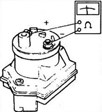
Fig. 7.3a Measuring the resistance of the primary winding (1984 models.)
4. Measure the resistance of the secondary winding of the coil between the terminal and the center wire terminal and compare it with the specification data.
5. The temperature of the coil during measurement should be around 20°C to avoid errors.
6. Replace the coil if necessary.
1986 and 1987 models
7. Disconnect the high-voltage and low-voltage wires.
8. Measure the winding resistance between terminals A and D and compare it with the specification data.
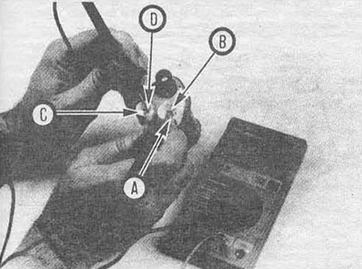
Fig. 7.3b Measuring the resistance of the primary winding (1985 model.)
9. Measure the secondary resistance between terminal A and the high-voltage contact.
10. The temperature of the coil during measurements should be about 20°C.
Models since 1988
11. Remove the distributor cap.
12. Loosen the screws securing the black-yellow and white-blue wires of the low-voltage coil inputs (terminals A and B respectively).
13. Measure the coil resistance between terminals A and B, compare with the specification data.
14. Measure the resistance of the secondary winding between terminal A and the high-voltage contact.
Replacement
Models 1964, 1985
15. Disconnect the negative cable from the battery.
16. Disconnect all wires from the coil.
17. Loosen the bracket clamp screw and remove the coil.
18. Install the coils in reverse order.
Models 1986, 1987
19. Disconnect the negative cable from the battery
20. Label all wires and disconnect them.
21. Unscrew the two mounting bolts and remove the coil.
22. Installation is carried out in the reverse order of removal.
Models since 1988
23. Disconnect the battery, remove the distributor cap (see Chapter 1).
24. Mark the positions of the black-yellow and white-blue wires, unscrew the screws and remove the wires
25. Unscrew the four mounting bolts and remove the coil from the housing.
26. Installation is carried out in the reverse order of removal.