
Gasoline engines (L13A) of the car Honda Civic 8

Engine specifications and characteristics
Engine characteristics Compression Cylinder head Cylinder block Lubrication system Cooling system Fuel and emission control system
Engine characteristics Compression Cylinder head Cylinder block Lubrication system Cooling system Fuel and emission control system

Lubricants and fluids for engines
*1: If genuine Honda MTF oil is not available, use API service grade SJ or higher grade oil with SAE 10W-30 viscosity as a temporary substitute. *2: We recommend genuine Honda brake fluid. Using brake fluid other than...
*1: If genuine Honda MTF oil is not available, use API service grade SJ or higher grade oil with SAE 10W-30 viscosity as a temporary substitute. *2: We recommend genuine Honda brake fluid. Using brake fluid other than...

Checking the idle mode
Note: Before checking the idle speed, check the following points: - the malfunction indicator lamp (MIL) does not come on and there are no DTCs in the system; - ignition timing; - spark plugs; - air filter; - PCV forced...
Note: Before checking the idle speed, check the following points: - the malfunction indicator lamp (MIL) does not come on and there are no DTCs in the system; - ignition timing; - spark plugs; - air filter; - PCV forced...
Computer Idle Diagnostic Procedure (ECM)
The idle speed diagnostic procedure must be performed to enter the engine idle speed characteristics into the ECM memory. Perform the idle computer diagnostic procedure whenever you perform the following actions:...
The idle speed diagnostic procedure must be performed to enter the engine idle speed characteristics into the ECM memory. Perform the idle computer diagnostic procedure whenever you perform the following actions:...

Checking engine compression
Note: You must reset the Engine Control Module (ECM) after completing this procedure, otherwise the ECM will continue to stop the injectors. Reset the ECM using the Honda Diagnostic System (HDS). 1. Warm up the engine...
Note: You must reset the Engine Control Module (ECM) after completing this procedure, otherwise the ECM will continue to stop the injectors. Reset the ECM using the Honda Diagnostic System (HDS). 1. Warm up the engine...

Checking and adjusting the belt drive
To check and adjust, you will need a special tool: a belt tension sensor (07JGG-0010101). Note: This check must be performed with the engine cold. Used belt 1. Remove the lower engine cover 2. Check the drive belt for...
To check and adjust, you will need a special tool: a belt tension sensor (07JGG-0010101). Note: This check must be performed with the engine cold. Used belt 1. Remove the lower engine cover 2. Check the drive belt for...

Checking engine oil pressure
Note: To perform the test, you will need special tools: a mounting adapter and an oil pressure gauge (07406-0030000). Note: If the low oil pressure indicator remains on while the engine is running, check the engine oil...
Note: To perform the test, you will need special tools: a mounting adapter and an oil pressure gauge (07406-0030000). Note: If the low oil pressure indicator remains on while the engine is running, check the engine oil...

Replacing the engine oil filter
Note: This procedure requires a special tool: an oil filter wrench (07HAA-PJ70100). 1. Remove the lower engine cover. 2. Remove the old oil filter using an oil filter wrench. 3. Check the filter to make sure the rubber...
Note: This procedure requires a special tool: an oil filter wrench (07HAA-PJ70100). 1. Remove the lower engine cover. 2. Remove the old oil filter using an oil filter wrench. 3. Check the filter to make sure the rubber...

Removal the oil pan
1. If the engine is removed from the vehicle, proceed to step 10. 2. Remove the drive belt (with air conditioning) 3. Disconnect the A/C compressor clutch connector, then remove the A/C compressor without disconnecting...
1. If the engine is removed from the vehicle, proceed to step 10. 2. Remove the drive belt (with air conditioning) 3. Disconnect the A/C compressor clutch connector, then remove the A/C compressor without disconnecting...

Installing the oil pan
1. Completely remove old sealant from the mating surface of the oil pan, bolts and bolt holes. 2. Clean and dry the mating surfaces of the oil pan. 3. Apply new sealant to the oil pan. 4. Apply sealant P/N 08C70-K0334M...
1. Completely remove old sealant from the mating surface of the oil pan, bolts and bolt holes. 2. Clean and dry the mating surfaces of the oil pan. 3. Apply new sealant to the oil pan. 4. Apply sealant P/N 08C70-K0334M...
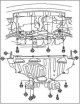
Removal the engine
Note: Cover the fenders to prevent damage to the paintwork. To avoid damaging wires and terminals, disconnect electrical connectors carefully, holding the connector by its body. Label all wire harnesses and hoses to...
Note: Cover the fenders to prevent damage to the paintwork. To avoid damaging wires and terminals, disconnect electrical connectors carefully, holding the connector by its body. Label all wire harnesses and hoses to...
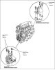
Engine installation
1. Install the attachment mounting brackets and tighten their mounting bolts to the required torque. 2. Position the engine/transmission assembly under the vehicle. Ensure that they are properly aligned. Carefully lower...
1. Install the attachment mounting brackets and tighten their mounting bolts to the required torque. 2. Position the engine/transmission assembly under the vehicle. Ensure that they are properly aligned. Carefully lower...

Removal the timing chain
1. Remove the front wheels. 2. Remove the lower engine cover. 3. Remove the drive belt. 4. Remove the cylinder head cover. 5. Set piston #1 to the top dead center (TDC) position. The "UP" mark A on the camshaft sprocket...
1. Remove the front wheels. 2. Remove the lower engine cover. 3. Remove the drive belt. 4. Remove the cylinder head cover. 5. Set piston #1 to the top dead center (TDC) position. The "UP" mark A on the camshaft sprocket...

Installing the timing chain
1. Set the crankshaft to the top dead center (TDC) position. Align the TDC mark A on the crankshaft sprocket with the pointer B on the oil pump. 2. Set piston #1 to TDC. The "UP" mark A on the camshaft sprocket should...
1. Set the crankshaft to the top dead center (TDC) position. Align the TDC mark A on the crankshaft sprocket with the pointer B on the oil pump. 2. Set piston #1 to TDC. The "UP" mark A on the camshaft sprocket should...

Removal and installation the crankshaft pulley
Removal 1. Remove the right front wheel. 2. Remove the lower engine cover. 3. Hold the pulley with handle A and pulley holding handle B. 4. Remove the bolt using a 19mm C socket and a pry bar, then remove the crankshaft...
Removal 1. Remove the right front wheel. 2. Remove the lower engine cover. 3. Hold the pulley with handle A and pulley holding handle B. 4. Remove the bolt using a 19mm C socket and a pry bar, then remove the crankshaft...

Installing the timing chain housing oil seal
1. Use special tools to install the new oil seal strictly perpendicularly into the timing chain housing to the specified depth. 2. Measure the distance between the timing chain housing surface and the oil seal. Height...
1. Use special tools to install the new oil seal strictly perpendicularly into the timing chain housing to the specified depth. 2. Measure the distance between the timing chain housing surface and the oil seal. Height...

Installing the cylinder head cover
1. Clean the cylinder head cover gasket and its groove thoroughly. 2. Insert cylinder head cover gasket A into the groove in cylinder head B. 3. Make sure the surfaces to be joined are clean and dry. 4. Apply a 3.0 mm...
1. Clean the cylinder head cover gasket and its groove thoroughly. 2. Insert cylinder head cover gasket A into the groove in cylinder head B. 3. Make sure the surfaces to be joined are clean and dry. 4. Apply a 3.0 mm...

Removal the rocker arm assembly of the cylinder head
1. Remove the cylinder head cover. 2. Loosen the rocker arm adjusting screws A. 3. Loosen the rocker shaft mounting bolts one by one, two turns each. 4. Remove the rocker arm shaft mounting bolts, then remove the rocker...
1. Remove the cylinder head cover. 2. Loosen the rocker arm adjusting screws A. 3. Loosen the rocker shaft mounting bolts one by one, two turns each. 4. Remove the rocker arm shaft mounting bolts, then remove the rocker...

Installing the cylinder head rocker arm block
1. Install rocker arm assembly A using dowel pin B. Note: When reassembling the rocker arms, install the rocker arms onto the shaft from the timing chain side. 2. Tighten the bolts in the sequence shown below, two turns...
1. Install rocker arm assembly A using dowel pin B. Note: When reassembling the rocker arms, install the rocker arms onto the shaft from the timing chain side. 2. Tighten the bolts in the sequence shown below, two turns...

Assembly/disassembly of the shaft and rocker arm of the cylinder head
Note: When removing parts, remember or mark each one so that you can reinstall them correctly later. When disassembling and reassembling the rocker arms, install the rocker arms on the shaft from the timing chain drive...
Note: When removing parts, remember or mark each one so that you can reinstall them correctly later. When disassembling and reassembling the rocker arms, install the rocker arms on the shaft from the timing chain drive...

Removal the cylinder head
Note: Cover the fenders to prevent damage to the paintwork. To avoid damage, disconnect electrical connectors carefully, holding the connector by its body. To prevent damage to the cylinder head, wait until the coolant...
Note: Cover the fenders to prevent damage to the paintwork. To avoid damage, disconnect electrical connectors carefully, holding the connector by its body. To prevent damage to the cylinder head, wait until the coolant...

Removal the cylinder head valve, spring, valve seals
Note: Mark the valves and valve springs as you remove them so you can return them to their original locations when reinstalling. 1. Remove the cylinder head. 2. Remove the camshaft. 3. Using a suitable size socket A and...
Note: Mark the valves and valve springs as you remove them so you can return them to their original locations when reinstalling. 1. Remove the cylinder head. 2. Remove the camshaft. 3. Using a suitable size socket A and...
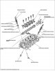
Checking the cylinder head valve
1. Remove the valves. 2. Measure each valve in the directions shown. Inlet valve dimensions A Standard (new): 31.85-32.15 mm. In Standard (new): 118.05-118.65 mm. C Standard (new): 5.48-5.49 mm. With Limit Value: 5.45...
1. Remove the valves. 2. Measure each valve in the directions shown. Inlet valve dimensions A Standard (new): 31.85-32.15 mm. In Standard (new): 118.05-118.65 mm. C Standard (new): 5.48-5.49 mm. With Limit Value: 5.45...

Checking the clearance between the cylinder head valve stem and the guide bushing
1. Remove the valves. 2. Pull the valve out of its guide bushing by about 10 mm, then measure the clearance between the valve stem and the guide bushing using a dial indicator while swinging the stem in a perpendicular...
1. Remove the valves. 2. Pull the valve out of its guide bushing by about 10 mm, then measure the clearance between the valve stem and the guide bushing using a dial indicator while swinging the stem in a perpendicular...

Replacing the cylinder head valve guide
1. Check the clearance between the valve stem and the guide bushing. 2. As shown in the figure below, use a commercially available pneumatic hammer-driven guide rod for fitting valve bushings A, modified to fit the...
1. Check the clearance between the valve stem and the guide bushing. 2. As shown in the figure below, use a commercially available pneumatic hammer-driven guide rod for fitting valve bushings A, modified to fit the...
This section is available on: russian, bulgarian, belarusian, ukrainian, serbian, croatian, romanian, polish, slovak, hungarian
Link in different formats to this section
TEXTHTMLBB Code
- General information
- Technical data
- Governing bodies
- Driving and maintenance
- Power unit
- Gasoline engines (L13A)
- Gasoline engines (R18A)
- Diesel engines (N22A)
- Cooling and lubrication (L13A)
- Cooling and lubrication (R18A)
- Cooling and lubrication (N22A)
- Injection system (gasoline)
- Injection system (diesel)
- Toxicity reduction system
- Troubleshooting
- Transmission
- Clutch and drive shafts
- Mechanical gearbox
- Chassis and running gear
- Suspension and wheels
- Steering
- Brake system
- Body and interior
- Exterior (external elements)
- Doors, locks and windows
- Electrical equipment
- Equipment and devices
- Headlights and lighting
- Power devices
- Electrical circuits
- General information
- User manual
- Maintenance
- Power unit
- Engines D15B and D17A
- K20A Engines
- Overhaul engine
- Cooling system
- Lubrication system
- Fuel injection system
- Toxicity reduction system
- Engine electrical equipment
- Transmission
- Clutch
- Manual gearbox
- Automatic gearbox
- Variator (CVT)
- Drive shafts
- Chassis and running gear
- Car suspension
- Steering
- Brake system
- Body and interior
- Exterior (external elements)
- Interior (internal elements)
- Doors, locks and windows
- Heater and air conditioner
- Manual air conditioner
- Automatic air conditioner
- Security system
- Electrical equipment
- Equipment and devices
- Headlights and lighting
- Windscreen wipers
- Audio system
- Electrical diagrams
- General information
- Introduction to guide
- User manual
- Maintenance
- Power unit
- Engine in car (Civic)
- Engine in car (Integra)
- Engine overhaul
- Cooling and heating
- Power and exhaust systems
- Engine electrical equipment
- Engine management systems
- Transmission
- Manual gearbox
- Automatic transmission (AT/CVT)
- Clutch and drive shafts
- Chassis and running gear
- Brake system
- Car suspension
- Steering
- Body and interior
- Exterior (external elements)
- Interior (internal elements)
- Doors, locks and windows
- Electrical equipment
- Equipment and devices
- Electrical circuits
- Power unit
- SOHC engines
- DOHC engines
- Engine overhaul
- Cooling and lubrication system
- Intake and exhaust system
- Fuel injection system (SOHC)
- Fuel injection system (DOHC)
- Carburetor
- Transmission
- Clutch
- Manual gearbox S4C
- Manual gearbox S40
- Automatic gearbox
- Drive shafts
- Chassis and running gear
- Car suspension
- Steering
- Brake system
- Body and interior
- Body elements
- Heater and air conditioner
- Electrical equipment
- Power devices
- Equipment and instruments
- Electrical circuits
- General information
- Maintenance
- Power unit
- Engine in a car
- Engine overhaul
- Cooling system
- Power and exhaust system
- Engine electrical equipment
- Emission control system
- Transmission
- Mechanical gearbox
- Automatic gearbox
- Clutch and drive shafts
- Four-wheel drive
- Chassis and running gear
- Brake system
- Car suspension
- Steering
- Body and interior
- Body elements
- Electrical equipment
- Equipment and devices
- Electrical circuits