
Attention: high voltage! Be careful when working with the ignition system.
The electronic ignition system consists of a key, a battery, a coil, a distributor, high-voltage wires and spark plugs (see fig. 5.1).
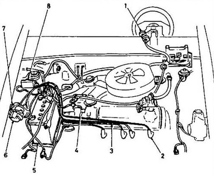
Pic. 5.1 Location of ignition system components:
1 key;
2 - candle;
3 - high-voltage wire;
4 - distributor;
5 - battery;
6 - coil;
7 - radio interference suppressor;
8 - main fuse.
The distributor is driven from the camshaft. On early models, the distributor was equipped with centrifugal and vacuum ignition timing controls. On later models, the ignition is controlled by an electronic module. Models with injection engines are equipped with Toy and Denso distributors, and carburetor models are with Hitachi and Gou and Denso distributors. Both assemblies are identical, the main difference is in the physical arrangement of components such as chopper, stator, magnet and reluctance (see fig. 5.2a and 5.2b).
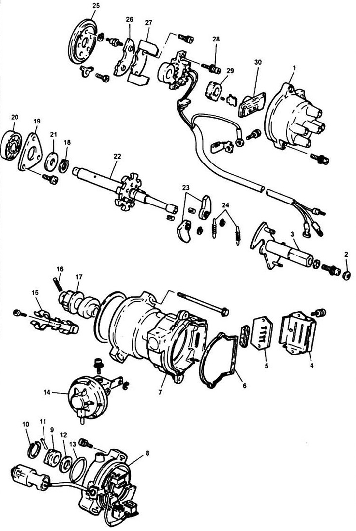
Pic. 5.2a Distributor TOYO DENSO
1 - distributor cap;
2 - cap;
3 - rotor shaft;
4 - breaker body;
5 - interrupter;
6 - cover gasket;
7 - distributor housing;
8 - sensor housing;
9 - clutch;
10 - holder;
11 - pin;
12 - thrust washer;
13 - rubber ring;
14 - diaphragm of the vacuum regulator;
15 - wire holder;
16 - stopper;
17 - rotor;
18 - lock washer;
19 - thrust board;
20 - bearing;
21 - thrust washer;
22 - shaft;
23 - centrifugal regulator weights;
24 - springs;
25 - breaker disk;
26 - magnet;
27 - stator;
28 - screw;
29 - magnetic resistance;
30 - rotor (slider).
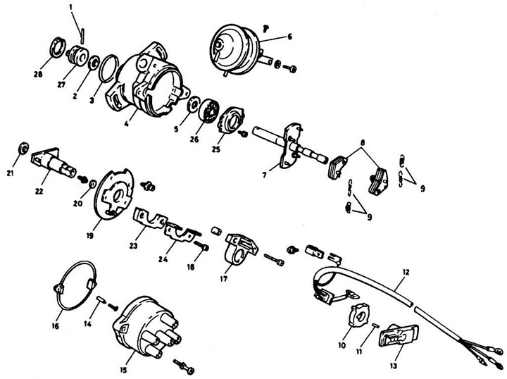
Pic. 5.2b Distributor HITACHI:
1 - pin;
2 - thrust washer;
3 - rubber ring;
4 - body;
5 - stuffing box;
6 - diaphragm of the vacuum regulator;
7 - shaft;
8 - centrifugal regulator weights;
9 - spring;
10 - magnetic resistance;
11 - pin;
12 - primary wire;
13 - rotor (slider);
14 - sealing contact;
15 - cover;
16 - rubber ring;
17 - sensor-breaker;
18 - screw;
19 - breaker disk;
20 - cap;
21 - thrust washer;
22 - rotor shaft;
23 - magnet;
24 - stator;
25 - thrust board;
26 - bearing;
27 - clutch;
28 - holder.
On models with injection since 1988, a shaft angle sensor is installed, which is located between the cylinder head and the distributor. On these models, a self-diagnostic system for the condition of injection and ignition systems is used. See Chapter 6 for self-diagnosis fault codes.