
Fuel injection system (SOHC) of vehicle Honda Civic 5 and 6


Self-diagnosis procedure
1. When the MIL comes on, do the following: 1. Connect the shorted SCS connector to the diagnostic connector (the two-pin diagnostic connector is located under the dashboard on the passenger side, closer to the door)....
1. When the MIL comes on, do the following: 1. Connect the shorted SCS connector to the diagnostic connector (the two-pin diagnostic connector is located under the dashboard on the passenger side, closer to the door)....

Removal the electronic engine control unit
If access to the ECM is required for individual voltage or resistance tests, remove the passenger side kick panel. Move the carpet back and remove the ECM mounting bolt. The drawing shown is for left-hand drive....
If access to the ECM is required for individual voltage or resistance tests, remove the passenger side kick panel. Move the carpet back and remove the ECM mounting bolt. The drawing shown is for left-hand drive....

Checking and adjusting the idle speed
Checking/adjusting Adjust the idle speed using a Honda tester. If this is not possible, check the following: Note: Before adjusting the idle speed, check the following items: The MIL lamp does not indicate a...
Checking/adjusting Adjust the idle speed using a Honda tester. If this is not possible, check the following: Note: Before adjusting the idle speed, check the following items: The MIL lamp does not indicate a...
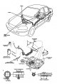

Fuel hose/quick couplings
Precautionary measures Do not smoke while working on the fuel system. Avoid open flames in the workplace. The fuel hose assembly with quick-release couplings serves to connect the fuel line and the fuel pump built into...
Precautionary measures Do not smoke while working on the fuel system. Avoid open flames in the workplace. The fuel hose assembly with quick-release couplings serves to connect the fuel line and the fuel pump built into...

Fuel system — description
The fuel system consists of a fuel tank, a high-pressure fuel pump, a main fuel injection relay, a fuel filter, a return valve, fuel injectors and fuel lines (supply and return).
The fuel system consists of a fuel tank, a high-pressure fuel pump, a main fuel injection relay, a fuel filter, a return valve, fuel injectors and fuel lines (supply and return).

Fuel pressure
Pressure relief Before disconnecting fuel lines or hoses, relieve pressure in the fuel system by loosening the service bolt on the top of the fuel filter. Do not smoke while working on the fuel system. Keep open flames...
Pressure relief Before disconnecting fuel lines or hoses, relieve pressure in the fuel system by loosening the service bolt on the top of the fuel filter. Do not smoke while working on the fuel system. Keep open flames...
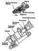
Fuel injectors — description
Fuel injectors have an electromagnetic drive and a fixed opening value, consist of a solenoid, a needle valve and a housing. When current flows through the solenoid winding, the valve needle rises, opening the passage...
Fuel injectors have an electromagnetic drive and a fixed opening value, consist of a solenoid, a needle valve and a housing. When current flows through the solenoid winding, the valve needle rises, opening the passage...

Check valve
Description The check valve maintains the pressure at the fuel injectors constant. When the pressure difference between the fuel and intake manifolds exceeds 250 kPa (2.55 kg/cm²) (engines D16Y4, D16Y9 - 294 kPa, 3.0...
Description The check valve maintains the pressure at the fuel injectors constant. When the pressure difference between the fuel and intake manifolds exceeds 250 kPa (2.55 kg/cm²) (engines D16Y4, D16Y9 - 294 kPa, 3.0...

Fuel filter
Replacement Attention: Do not smoke while working on the fuel system. Avoid open flames in the workplace. When replacing the fuel filter, be careful to keep it away from the battery terminals and other tools. The fuel...
Replacement Attention: Do not smoke while working on the fuel system. Avoid open flames in the workplace. When replacing the fuel filter, be careful to keep it away from the battery terminals and other tools. The fuel...

Fuel pump
Examination Warning: Do not smoke during the test. Do not allow open flames in the work area. If you suspect a faulty fuel pump, you can check its operation. In the ignition position OM, you can hear a characteristic...
Examination Warning: Do not smoke during the test. Do not allow open flames in the work area. If you suspect a faulty fuel pump, you can check its operation. In the ignition position OM, you can hear a characteristic...

Inertia switch (models KG, KE, KS, KR)
Description The inertia switch is a safety device that shuts off the fuel supply in the event of an accident or collision. The switch is located behind the glove compartment. After a collision, the switch must be reset...
Description The inertia switch is a safety device that shuts off the fuel supply in the event of an accident or collision. The switch is located behind the glove compartment. After a collision, the switch must be reset...

Main relay of the injection system
Description The main relay of the injection system consists of two independent relays. The relay is located on the passenger side of the hood. The first relay is triggered when the ignition is turned on and powers the...
Description The main relay of the injection system consists of two independent relays. The relay is located on the passenger side of the hood. The first relay is triggered when the ignition is turned on and powers the...

Fuel tank
Replacement Caution: Do not smoke while working on the fuel system. Keep open flames away from the work area. 1. Relieve fuel pressure. 2. Remove the seat cushion. 3. Remove the access hatch on the floor. 4. Disconnect...
Replacement Caution: Do not smoke while working on the fuel system. Keep open flames away from the work area. 1. Relieve fuel pressure. 2. Remove the seat cushion. 3. Remove the access hatch on the floor. 4. Disconnect...

Air filter of the air intake system
Replacing the filter element Note: Do not blow out the filter element with compressed air (except for models KR, KY, KW, KT, KV).
Replacing the filter element Note: Do not blow out the filter element with compressed air (except for models KR, KY, KW, KT, KV).

Throttle drive cable
Inspection/Adjustment 1. Start the engine. Maintain the engine speed at 3000 rpm without any load on the engine (gearbox in neutral, automatic transmission selector in position [P] or [N]) until the electric fan turns...
Inspection/Adjustment 1. Start the engine. Maintain the engine speed at 3000 rpm without any load on the engine (gearbox in neutral, automatic transmission selector in position [P] or [N]) until the electric fan turns...

Throttle body — check
Caution: Do not attempt to adjust the throttle stop screw. It is factory set. 1. Start the engine. Maintain the engine speed at 3000 rpm without any load on the engine (gearbox in neutral, automatic transmission...
Caution: Do not attempt to adjust the throttle stop screw. It is factory set. 1. Start the engine. Maintain the engine speed at 3000 rpm without any load on the engine (gearbox in neutral, automatic transmission...

Throttle body — removal and disassembly
Warning: The throttle stop lock screw is not adjustable. After overhaul, adjust the throttle cable. The throttle position sensor cannot be removed. Disassembly
Warning: The throttle stop lock screw is not adjustable. After overhaul, adjust the throttle cable. The throttle position sensor cannot be removed. Disassembly
Description of the exhaust gas toxicity reduction system
The exhaust gas toxicity reduction system includes a three-way catalytic converter, crankcase ventilation system, and a fuel vapor removal system.
The exhaust gas toxicity reduction system includes a three-way catalytic converter, crankcase ventilation system, and a fuel vapor removal system.

Emission Control System — Exhaust
Examination Warning: Do not smoke while performing this operation. Keep open flames away from the work area. 1. Connect the tachometer. 2. Start the engine. Maintain the engine speed at 3000 rpm without any load on the...
Examination Warning: Do not smoke while performing this operation. Keep open flames away from the work area. 1. Connect the tachometer. 2. Start the engine. Maintain the engine speed at 3000 rpm without any load on the...

Three-way catalytic converter
Examination If increased exhaust pressure is detected, remove the catalytic converter and visually inspect it for clogging, melting, or chipping of the working material. Replace the catalytic converter if any signs are...
Examination If increased exhaust pressure is detected, remove the catalytic converter and visually inspect it for clogging, melting, or chipping of the working material. Replace the catalytic converter if any signs are...

Crankcase ventilation system
Description The positive crankcase ventilation (PSV) is designed to prevent crankcase gases from entering the atmosphere. The PSV valve contains a spring-loaded plunger. When the engine is started, the plunger rises...
Description The positive crankcase ventilation (PSV) is designed to prevent crankcase gases from entering the atmosphere. The PSV valve contains a spring-loaded plunger. When the engine is started, the plunger rises...

Fuel vapor removal system
Examination (except for engines D14A3, D14A4) 1. Remove the fuel tank cap. 2. Start the engine and let it idle. 3. Disconnect the vacuum hose from the evaporative emission control valve and connect the vacuum gauge to...
Examination (except for engines D14A3, D14A4) 1. Remove the fuel tank cap. 2. Start the engine and let it idle. 3. Disconnect the vacuum hose from the evaporative emission control valve and connect the vacuum gauge to...
This section is available on: russian, bulgarian, belarusian, ukrainian, serbian, croatian, romanian, polish, slovak, hungarian
Link in different formats to this section
TEXTHTMLBB Code
- General information
- Technical data
- Governing bodies
- Driving and maintenance
- Power unit
- Gasoline engines (L13A)
- Gasoline engines (R18A)
- Diesel engines (N22A)
- Cooling and lubrication (L13A)
- Cooling and lubrication (R18A)
- Cooling and lubrication (N22A)
- Injection system (gasoline)
- Injection system (diesel)
- Toxicity reduction system
- Troubleshooting
- Transmission
- Clutch and drive shafts
- Mechanical gearbox
- Chassis and running gear
- Suspension and wheels
- Steering
- Brake system
- Body and interior
- Exterior (external elements)
- Doors, locks and windows
- Electrical equipment
- Equipment and devices
- Headlights and lighting
- Power devices
- Electrical circuits
- General information
- User manual
- Maintenance
- Power unit
- Engines D15B and D17A
- K20A Engines
- Overhaul engine
- Cooling system
- Lubrication system
- Fuel injection system
- Toxicity reduction system
- Engine electrical equipment
- Transmission
- Clutch
- Manual gearbox
- Automatic gearbox
- Variator (CVT)
- Drive shafts
- Chassis and running gear
- Car suspension
- Steering
- Brake system
- Body and interior
- Exterior (external elements)
- Interior (internal elements)
- Doors, locks and windows
- Heater and air conditioner
- Manual air conditioner
- Automatic air conditioner
- Security system
- Electrical equipment
- Equipment and devices
- Headlights and lighting
- Windscreen wipers
- Audio system
- Electrical diagrams
- General information
- Introduction to guide
- User manual
- Maintenance
- Power unit
- Engine in car (Civic)
- Engine in car (Integra)
- Engine overhaul
- Cooling and heating
- Power and exhaust systems
- Engine electrical equipment
- Engine management systems
- Transmission
- Manual gearbox
- Automatic transmission (AT/CVT)
- Clutch and drive shafts
- Chassis and running gear
- Brake system
- Car suspension
- Steering
- Body and interior
- Exterior (external elements)
- Interior (internal elements)
- Doors, locks and windows
- Electrical equipment
- Equipment and devices
- Electrical circuits
- Power unit
- SOHC engines
- DOHC engines
- Engine overhaul
- Cooling and lubrication system
- Intake and exhaust system
- Fuel injection system (SOHC)
- Fuel injection system (DOHC)
- Carburetor
- Transmission
- Clutch
- Manual gearbox S4C
- Manual gearbox S40
- Automatic gearbox
- Drive shafts
- Chassis and running gear
- Car suspension
- Steering
- Brake system
- Body and interior
- Body elements
- Heater and air conditioner
- Electrical equipment
- Power devices
- Equipment and instruments
- Electrical circuits
- General information
- Maintenance
- Power unit
- Engine in a car
- Engine overhaul
- Cooling system
- Power and exhaust system
- Engine electrical equipment
- Emission control system
- Transmission
- Mechanical gearbox
- Automatic gearbox
- Clutch and drive shafts
- Four-wheel drive
- Chassis and running gear
- Brake system
- Car suspension
- Steering
- Body and interior
- Body elements
- Electrical equipment
- Equipment and devices
- Electrical circuits