
Contents: Adjusting the rod clearance ⇊ Examination ⇊ Table. Pressure in the main brake…⇊ Removal and installation ⇊
Adjusting the rod clearance
1. Install the special tool (A) on the master cylinder. Turn the adjusting nut (D) to set the rod (B) so that it touches piston No.2 (C) of the master cylinder.
Note: Make sure that the special tool is installed on the brake master cylinder without any clearance (E).
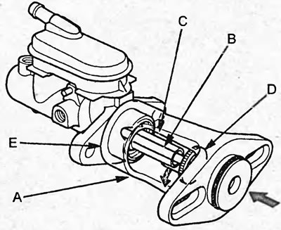
2. Without changing the position of the rod, install the special tool (A) on the brake booster and tighten the nuts.
Tightening torque - 15 Nm
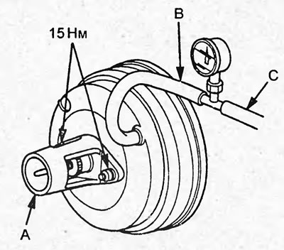
3. Install the vacuum gauge by connecting the hoses (B and C) as shown in the figure.
4. Start the engine and wait until the engine warms up (the cooling system fan should turn on 2 times).
5. By adjusting the engine crankshaft speed with the accelerator pedal, set the vacuum shown by the vacuum gauge to 66.7 kPa.
6. Using the feeler gauge (A), measure the gap between the adjusting nut (B) and the special tool body.
Gap - 0-0.4 mm
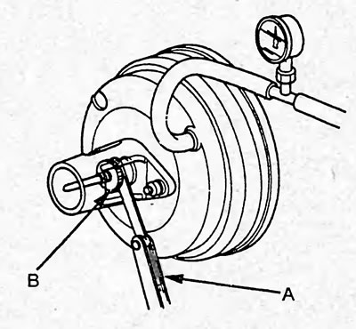
If the gap between the adjusting nut and the body of the special device is 0.4 mm, then the gap between the rod and piston No.2 is 0 mm and no adjustment is required.
If the gap between the adjusting nut and the body of the special device is 0 mm, then the gap between the rod and piston No.2 is 0.4 mm or more and adjustment is necessary.
7. Adjust the gap.
a) Loosen the lock nut (A) and, by turning the adjusting nut (C), adjust the gap.
Note:
- Adjustment should be carried out when a vacuum of 66.7 kPa has been created in the brake booster.
- Hold the fork (B) during adjustment.
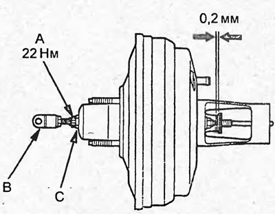
b) Tighten the lock nut.
Tightening torque: 22 Nm
8. Remove the special device.
Examination
Without using devices
Note: If the brake booster is found to be not operating properly, replace the brake booster assembly.
Step 1
1. Start the engine.
2. Wait until the engine warms up - the cooling system fan should turn on and off 2 times.
3. Turn off the engine.
4. Press the brake pedal several times with normal force.
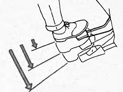
5. If the pedal stroke is long when first pressed, but becomes shorter with subsequent presses, no faults in the vacuum booster have been detected.
Note: If any faults are found, check the vacuum hose or check valve and check their installation. If faults are found, repair them and recheck the brake booster operation.
Step 2
1. Start the engine.
2. Press the brake pedal with normal force.
3. Keeping the pedal depressed, turn off the engine.
4. Keep the pedal depressed for approximately 30 seconds.
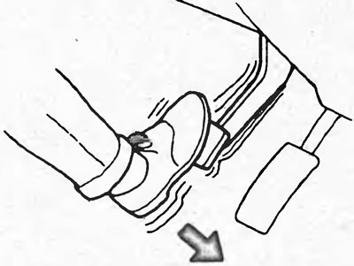
5. If the pedal height has not changed, no faults in the vacuum booster have been detected.
Using instruments
1. Checking the reduction in vacuum.
a) Connect the vacuum gauge as shown in the figure.
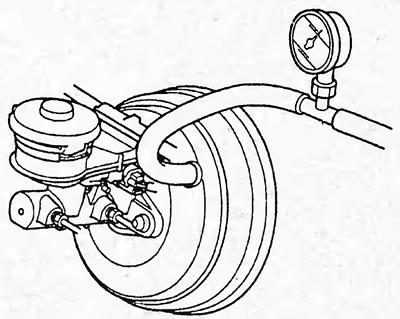
b) Start the engine and wait until the engine warms up - the cooling fan should turn on and off 2 times.
c) By adjusting the engine crankshaft speed with the accelerator pedal, set the vacuum indicated by the vacuum gauge to 66.7 kPa.
d) Stop the engine and observe the vacuum gauge readings for 30 seconds.
Vacuum reduction - no more than 2.7 kPa (within 30 seconds)
If the vacuum reduction is not within normal limits, check the following items:
- vacuum hose with check valve;
- vacuum tubes and hoses;
- vacuum brake booster;
- master brake cylinder;
- the piston rod seal and the piston cuff of the master brake cylinder.
2. Check the pressure in the master cylinder.
a) Connect the vacuum gauge as shown in the figure.
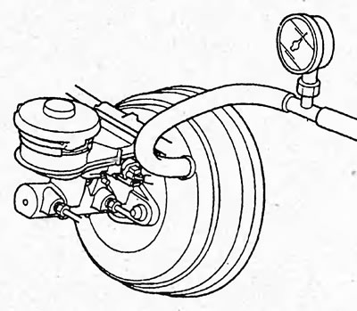
b) Connect the pressure gauges as shown in the figure.
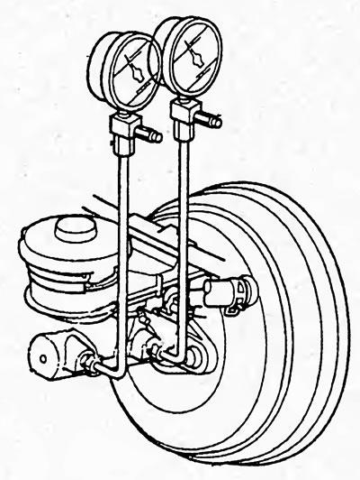
c) Pump the assembled system.
d) Start the engine and set it to idle speed.
d) Install the brake pedal force gauge on the brake pedal and press the brake pedal with a force of 98 N and read the pressure gauges. Measure the pressure when pressing the brake pedal with a force of 294 N.
e) By adjusting the engine crankshaft speed with the accelerator pedal, set the vacuum shown by the vacuum gauge to 66.7 kPa.
g) Repeat the measurements described in subparagraph "d".
h) Compare the measured values with those given in the table "Pressure in the master brake cylinder".
If the pressure is not as shown in the table, check the master cylinder.
Table. Pressure in the main brake cylinder.
| Model | Vacuum pressure in brake booster, kPa | Pedal force, N | Pressure, kPa |
| 2WD Sedan with Rear Drum Brakes | 0 | 98 | 0 |
| 294 | 1800 | ||
| 66,7 | 98 | 4870 | |
| 294 | 9670 | ||
| 2WD Sedan with Rear Disc Brakes | 0 | 98 | 0 |
| 294 | 1450 | ||
| 66,7 | 98 | 4320 | |
| 294 | 8970 | ||
| Sedan 4WD | 0 | 98 | 0 |
| 294 | 1560 | ||
| 66,7 | 98 | 4200 | |
| 294 | 10310 | ||
| 5-door hatchback with D15B engine (SOHC) | 0 | 98 | 0 |
| 294 | 1800 | ||
| 66,7 | 98 | 5020 | |
| 294 | 8680 | ||
| 5-door hatchback with engines D15B and D17A (SOHC VTEC) | 0 | 98 | 0 |
| 294 | 1710 | ||
| 66,7 | 98 | 4580 | |
| 294 | 10440 |
Removal and installation
Sedan
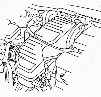
1. Remove the air filter housing.
2. Remove the brake master cylinder (see section "Master brake cylinder").
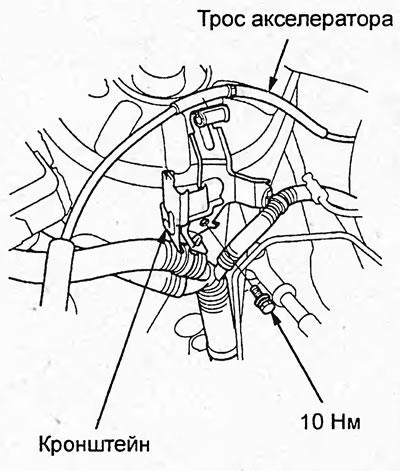
3. Loosen the bolts and remove the accelerator cable bracket.
4. (Models with manual transmission) Loosen the bolt and remove the clutch hydraulic tube bracket.
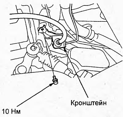
5. Loosen the bolt and remove the vacuum tube.
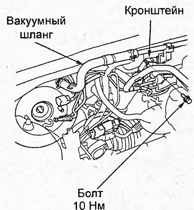
6. Disconnect the vacuum hose from the brake booster.
7. Remove the cotter pin, take out the fork axle and disconnect the fork from the brake pedal.
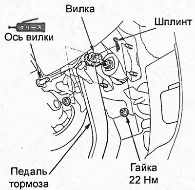
8. Loosen the brake booster mounting nuts.
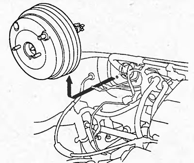
9. Remove the brake booster.
Note:
- Installation is carried out in the reverse order of removal.
- When installing:
- before installing the master cylinder, check and, if necessary, adjust the clearance of the master cylinder rod;
- use only new cotter pin.
- After installation:
- fill the brake fluid reservoir with brake fluid and bleed the brake system;
- check and, if necessary, adjust the height and free travel of the brake pedal.
Hatchback
1. Remove the air filter housing.
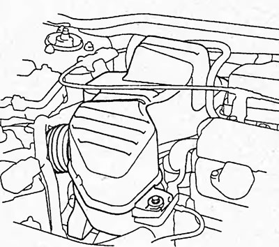
2. Remove the brake master cylinder (see section "Master brake cylinder").
3. Loosen the bolts and remove the accelerator cable bracket and engine wiring harness.
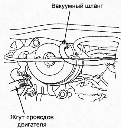
4. Disconnect the vacuum hose from the brake booster.
5. Remove the cotter pin, take out the fork axle and disconnect the fork from the brake pedal.
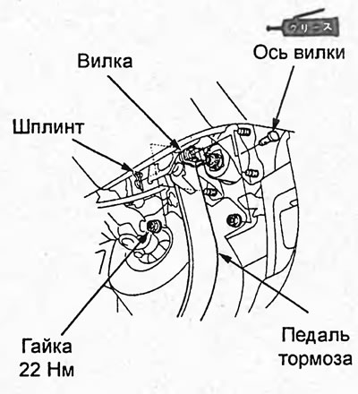
6. Loosen the brake booster mounting nuts.
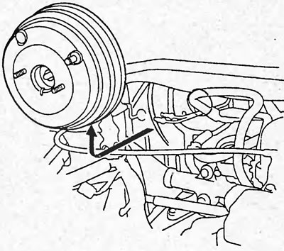
7. Remove the brake booster (A).
Note:
- Installation is carried out in the reverse order of removal.
- When installing:
- before installing the master cylinder, check and, if necessary, adjust the clearance of the master cylinder rod;
- use only new cotter pin.
- After installation:
- fill the brake fluid reservoir with brake fluid and bleed the brake system;
- check and, if necessary, adjust the height and free travel of the brake pedal.
(The text can be found on the website: «HondaBook.ru»)