
HondaBook.ru
Auto companies Volkswagen Auto companies Ford Auto companies Lada Auto companies Skoda Auto companies BMW Auto companies Mazda Auto companies Peugeot
English Русский
Български
Беларускі
Український
Српски
Hrvatski
Română
Polski
Slovenský
Magyar
Bookmark Contacts Sitemap   


Accord Civic Fit / Jazz CR-V HR-V Others Articles
Civic 3 and 4 (1983-1991) Civic 5 and 6 (1991-2000) Civic 6 (1995-2000) Civic 7 (2000-2005) Civic 8 (2005-2011)

Brake Master Cylinder (Hatchback) (Honda Civic 7)

  • Main
  • Honda Civic
  • 7 (2000-2005)
  • Chassis and running gear
  • Brake system
  • Brake Master Cylinder (Hatchback)
0
Contents: Removal and installation ⇊ Disassembly ⇊ Assembly ⇊
Removal and installation the master brake…

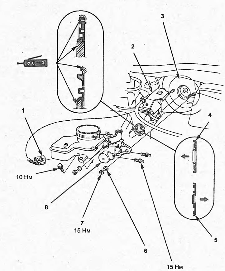
Removal and installation the master brake cylinder. 1 - low brake fluid level sensor connector, 2 - bracket, 3 - brake booster, 4 - oil seal (models with double vacuum booster), 5 - oil seal (models with single vacuum booster), 6 - spring washer, 7 - nut, 8 - master brake cylinder.


Removal and installation


Note: When removing parts, refer to the figure "Removing and installing the brake master cylinder".


1. Remove the brake fluid reservoir cap.

2. Pump out the brake fluid from the reservoir.

3. Disconnect the low brake fluid level sensor connector.

4. Disconnect the brake fluid pipes and install plugs on them.

Tightening torque - 15 Nm

5. Loosen the nuts and remove the master cylinder from the brake booster.

Tightening torque - 15 Nm

6. Remove the oil seal.

Note:

- Installation is carried out in the reverse order of removal.

- When installing:
  • position the seal so that the grooved side faces the master cylinder and the flat side faces the brake booster;
  • apply grease to the seal;
  • adjust the master cylinder piston clearance.

- After installation:
  • pour brake fluid into the reservoir and bleed the brake system;
  • check and, if necessary, adjust the height and free travel of the brake pedal.


Disassembly


1. Remove the oil seal.

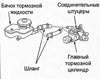
2. Disconnect the hoses from the reservoir and the master cylinder.
2. Disconnect the hoses from the reservoir and…


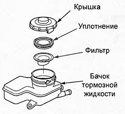
3. Remove the brake fluid reservoir cap, then remove the seal from the cap.
3. Remove the brake fluid reservoir cap, then…


4. Remove the filter from the brake fluid reservoir.

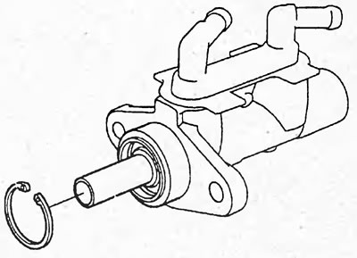
5. Press piston No.2 and, holding the piston pressed, remove the retaining ring.
5. Press piston No.2 and, holding the piston…


6. Remove the fittings and connecting sleeves.
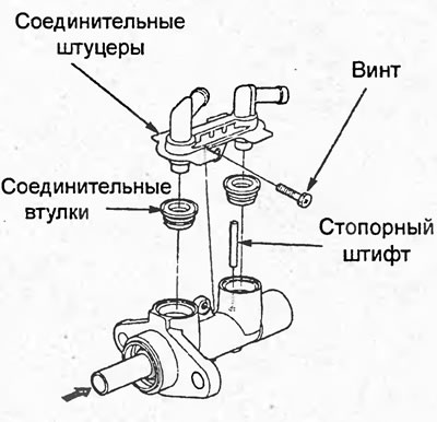


6. Remove the fittings and connecting sleeves.


7. Press piston No.2 and, while holding the piston pressed, remove the locking pin.

8. Remove the piston guide (dual amp models), piston no. 2 and piston no. 1.
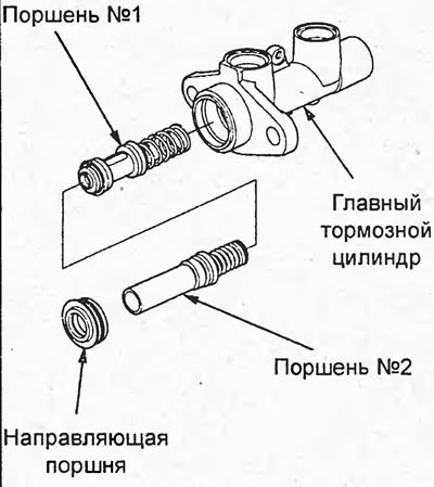
8. Remove the piston guide (dual amp models),…


Assembly


1. Install the seal on the brake fluid reservoir cap.

2. Install the filter on the brake fluid reservoir.

3. Lubricate the piston No.1 seals with brake fluid and install piston No.1 into the master brake cylinder.

Note: Before installation, make sure the valve moves smoothly and without sticking.
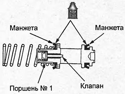

Note: Before installation, make sure the valve…


4. Lubricate the piston seals No.2 with brake fluid.
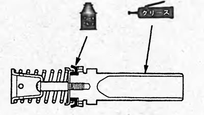


Models with dual brake booster.
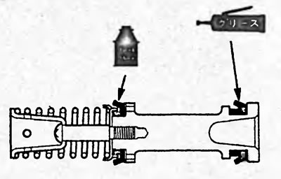
Models with dual brake booster.


Models with single brake booster.

Models with single brake booster.


5. Apply grease to:
  • (Models with dual brake booster) piston surface no.2;
  • (Models with single brake booster) piston cuff No.2.

6. Install piston No.2 into the master cylinder.

7. (Models with dual brake booster) Apply grease to the piston guide surfaces shown in the illustration.
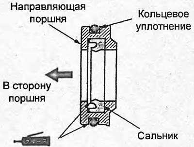
7. (Models with dual brake booster) Apply grease…


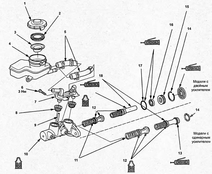
Master brake cylinder. 1 - brake fluid reservoir…

Master brake cylinder. 1 - brake fluid reservoir cap, 2 - cover seal, 3 - filter, 4 - brake fluid reservoir, 5 - hoses, 6 - screw, 7 - nipples, 8 - connecting sleeves, 9 - locking pin, 10 - brake master cylinder housing, 11 - piston No.1, 12, 13 - piston cuff, 14 - retaining ring, 15 - piston guide, 16 - piston cuff, 17 - ring seal, 18 - piston No.2.


8. Install the pistons and piston guide (models with double vacuum booster).
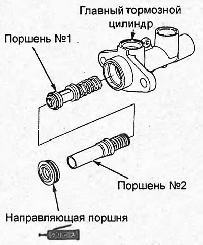
8. Install the pistons and piston guide (models…


9. Pressing on piston No.2, align the hole in the piston with the hole in the locking pin and install the locking pin.
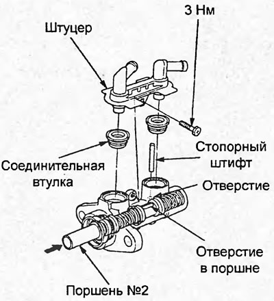
9. Pressing on piston No.2, align the hole in the…


10. Install the connecting sleeves onto the fittings.

11. Install the fittings on the master cylinder.

12. Press down on piston No.2 and, while holding it, install the retaining ring.
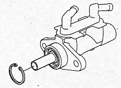
12. Press down on piston No.2 and, while holding…


13. Adjust the clearance of the master brake cylinder piston rod (see the subsection "Adjusting the piston rod clearance" of the section "Vacuum brake booster").


14. Connect the hoses to the fittings and the brake fluid reservoir. When installing, align the marks on the hoses and fittings.

14. Connect the hoses to the fittings and the…


15. Align the marks and connect the hoses to the tank and fittings.
This article is available at: russian, bulgarian, belarusian, ukrainian, serbian, croatian, romanian, polish, slovak, hungarian
This information has been verified: Yaroslav Shiryaev
Share with friends:
◀ Previous
Civic 7: Brake system
Next ▶

Master Brake Cylinder (Sedan)
Brake pedal
Checking the vacuum hose
Bleeding the brake system
Vacuum brake booster
Front brake mechanisms
Rear disc brakes
Rear drum brakes
Disassembly and assembly of the working brake cylinder
See also other articles from Honda manuals:
Master brake cylinder Honda Accord 3 (1985-1989)
Master Brake Cylinder — Removal and Installation Honda Fit 1 (2001-2008)
Brake master cylinder Honda CR-V 1 (1995-2001, petrol)
Master cylinder, brake booster — removal and installation Honda HR-V 1 (1998-2006, petrol)
Master Cylinder and Brake Booster — Removal and Installation Honda Avancier 1 (1999-2003, petrol)
Link in different formats to this article
Comments and feedback from visitors
No comments yet


How much will 13 + 40 ?


Civic 8 (2005-2011) 
  • General information
  • Technical data
  • Governing bodies
  • Driving and maintenance
  • Power unit
  • Gasoline engines (L13A)
  • Gasoline engines (R18A)
  • Diesel engines (N22A)
  • Cooling and lubrication (L13A)
  • Cooling and lubrication (R18A)
  • Cooling and lubrication (N22A)
  • Injection system (gasoline)
  • Injection system (diesel)
  • Toxicity reduction system
  • Troubleshooting
  • Transmission
  • Clutch and drive shafts
  • Mechanical gearbox
  • Chassis and running gear
  • Suspension and wheels
  • Steering
  • Brake system
  • Body and interior
  • Exterior (external elements)
  • Doors, locks and windows
  • Electrical equipment
  • Equipment and devices
  • Headlights and lighting
  • Power devices
  • Electrical circuits
Civic 7 (2000-2005) 
  • General information
  • User manual
  • Maintenance
  • Power unit
  • Engines D15B and D17A
  • K20A Engines
  • Overhaul engine
  • Cooling system
  • Lubrication system
  • Fuel injection system
  • Toxicity reduction system
  • Engine electrical equipment
  • Transmission
  • Clutch
  • Manual gearbox
  • Automatic gearbox
  • Variator (CVT)
  • Drive shafts
  • Chassis and running gear
  • Car suspension
  • Steering
  • Brake system
  • Body and interior
  • Exterior (external elements)
  • Interior (internal elements)
  • Doors, locks and windows
  • Heater and air conditioner
  • Manual air conditioner
  • Automatic air conditioner
  • Security system
  • Electrical equipment
  • Equipment and devices
  • Headlights and lighting
  • Windscreen wipers
  • Audio system
  • Electrical diagrams
Civic 6 (1995-2000) 
  • General information
  • Introduction to guide
  • User manual
  • Maintenance
  • Power unit
  • Engine in car (Civic)
  • Engine in car (Integra)
  • Engine overhaul
  • Cooling and heating
  • Power and exhaust systems
  • Engine electrical equipment
  • Engine management systems
  • Transmission
  • Manual gearbox
  • Automatic transmission (AT/CVT)
  • Clutch and drive shafts
  • Chassis and running gear
  • Brake system
  • Car suspension
  • Steering
  • Body and interior
  • Exterior (external elements)
  • Interior (internal elements)
  • Doors, locks and windows
  • Electrical equipment
  • Equipment and devices
  • Electrical circuits
Civic 5 and 6 (1991-2000) 
  • Power unit
  • SOHC engines
  • DOHC engines
  • Engine overhaul
  • Cooling and lubrication system
  • Intake and exhaust system
  • Fuel injection system (SOHC)
  • Fuel injection system (DOHC)
  • Carburetor
  • Transmission
  • Clutch
  • Manual gearbox S4C
  • Manual gearbox S40
  • Automatic gearbox
  • Drive shafts
  • Chassis and running gear
  • Car suspension
  • Steering
  • Brake system
  • Body and interior
  • Body elements
  • Heater and air conditioner
  • Electrical equipment
  • Power devices
  • Equipment and instruments
  • Electrical circuits
Civic 3 and 4 (1983-1991) 
  • General information
  • Maintenance
  • Power unit
  • Engine in a car
  • Engine overhaul
  • Cooling system
  • Power and exhaust system
  • Engine electrical equipment
  • Emission control system
  • Transmission
  • Mechanical gearbox
  • Automatic gearbox
  • Clutch and drive shafts
  • Four-wheel drive
  • Chassis and running gear
  • Brake system
  • Car suspension
  • Steering
  • Body and interior
  • Body elements
  • Electrical equipment
  • Equipment and devices
  • Electrical circuits
HondaBook.ru © 2018–2026 • Mobile version • Sitemap: EN BG BY UA RS HR RO PL SK HU • Feedback • Driver Information • Search system • Bookmark
Accord 3 (1985-1989) • Accord 6 (1997-2002) • Civic 3 and 4 (1983-1991) • Civic 5 and 6 (1991-2000) • Civic 6 (1995-2000) • Civic 7 (2000-2005) • Civic 8 (2005-2011) • Fit 1 (2001-2008) • CR-V 1 (1995-2001) • CR-V 2 (2002-2006) • HR-V 1 (1998-2006) • Avancier 1 (1999-2003) •
 
This website uses cookies to ensure proper functioning. By clicking "OK," you agree.