
Models up to 1988
1. On these models, the angle encoder consists of two individual encoders: "TDC" And "cylinder". Sensor "cylinder" defines the position of the first cylinder as the base for counting the injection sequence. The TDC sensor determines the injection start angle and generates a signal about the engine speed for the EMU.
2. To control the sensor "cylinder" Disconnect the distributor connector and measure the resistance between the white and red pins of the connector. Compare the measurement data with the values given in the specification.
3. To control the sensor "TDC" Disconnect the distributor connector and measure the resistance between the brown and blue connector pins. Compare the measurement data with the values given in the specification.
Models since 1988
4. Turn off the ignition.
5. Remove the fuse "HAZARD" from the fuse panel for 10 seconds to reset the EMU memory.
6. Start the engine and check that the indicator "CHECK ENGINE" blinking.
7. Stop the engine and disconnect an electric socket on the distributor.
8. With a two-point injection system, measure the resistance between pins D and E, then between B and C (see fig. 5.8a). For multipoint injection, measure the resistance between terminals C and D, then A and B (see fig. 5.8b). Compare instrument readings with specification data.
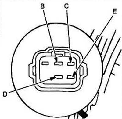
Pic. 5.8a. The location of the contacts of the distributor connector for two-point injection
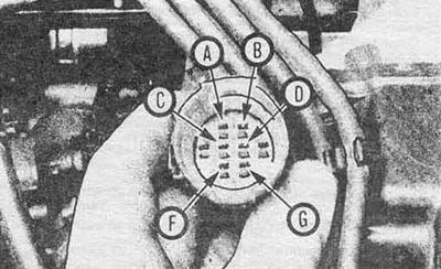
Pic. 5.8b Arrangement of contacts of the distributor connector with multi-point injection
9. Check continuity from pins E, D, B and C (two point injection) or from contacts C, D, A and B (multipoint injection) To "mass". Conductivity should be
10. If the EMU lamps display code 9, measure the resistance between terminals F and G. Compare with the specification data.
11. Check continuity from terminals F and G to "mass". Conductivity should be
12. In case of difficulty, contact a service station.
Replacement
13. In case of a negative result of any of the above tests, replace the distributor (see chapter 5).