
General description
1. The fuel vapor recovery system collects fuel vapors and, during engine operation, mixes them with the finished fuel-air mixture.
2. The vapor accumulator is a container filled with activated carbon. The information below will help you understand how the system works
Models with a carburetor
Note: This describes the operation of a typical EVAP system. On a particular car, some non-fundamental differences are possible.
3. The fuel tank cap is designed as a two-way valve, which ensures the safety of operation in case of failure of the fuel vapor recovery system.
4. Another 2-way valve mounted on the tank controls the flow of fuel vapor from the tank to the fuel accumulator and operates on the difference in fuel vapor pressure as the temperature changes.
5. Fuel vapors after the two-way valve enter the accumulator located in the engine compartment.
6. When the engine is turned off, the carburetor cut-off valve communicates the cavity of the float chamber with the vapor accumulator.
7. When the engine warms up, the thermal valve at the top of the accumulator will close, respectively, the relief diaphragm will open under the vacuum pressure in the intake manifold.
8. When the engine is turned off, the fuel supply through the main metering system is turned off by an electrovalve and prevents fuel from entering the carburetor diffuser.
Fuel injected models
9. When the fuel vapor pressure in the tank exceeds the set level, the two-way valve will open and fuel vapor will flow into the accumulator.
10. The battery stores fuel vapors until they are fed into the engine.
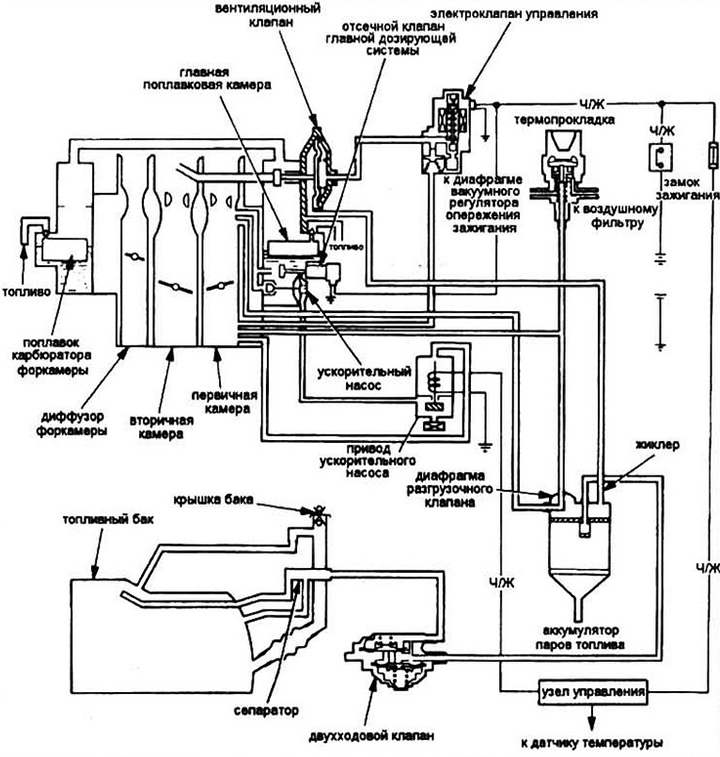
Pic. 10.1a Typical diagram of a fuel vapor recovery system (carbureted engines)
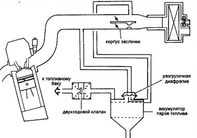
Pic. 10.1b Typical fuel vapor recovery scheme (models with injection)
11. The battery is unloaded through a diaphragm controlled by a thermal valve: up to a coolant temperature of 55 degrees Celsius, vacuum is not supplied from the intake manifold to the diaphragm, when this temperature is exceeded, the diaphragm opens and the battery is blown with fresh air, carrying fuel from the battery into the throttle space.
Control
Note: The possibility of failure of the evaporative emission system is very low. In this case, the hoses and the fuel vapor accumulator usually fail.
Hoses
12. Inspect the hoses first of all according to the connection diagram fixed inside the engine compartment, usually on the hood. Replace damaged hoses.
Battery
13. Remove the battery from the vehicle.
14. Warm up the engine and set its speed to 2500 rpm. When the battery is working properly, you should feel suction. Otherwise, replace the battery.
15. Disconnect the inlet hose and plug the outlet opening with your finger.