
Note: Piston rings must be replaced.
2. Using a special tool, remove the rings from the pistons – try not to accidentally damage the walls of the latter.
3. Scrape off any traces of carbon deposits from the piston crowns. After removing the bulk of the deposits, hand-clean the surface with a wire brush or a piece of fine-grit sandpaper.
Warning! Never use wire attachments for an electric drill to clean pistons made of soft material and easily subject to erosion!
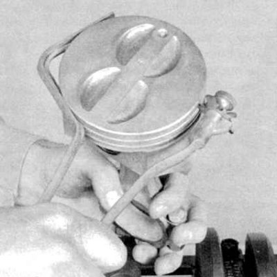
4a. Using a special tool, clean the ring grooves on the pistons (see accompanying illustration).
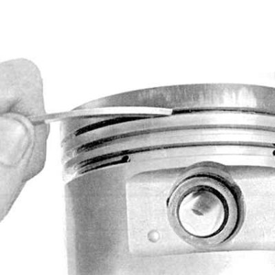
4b. Alternatively, you can use a piece of an old piston ring for this purpose (see accompanying illustration), however, be careful not to scratch the bottom and walls of the groove or cut your fingers. 5. After removing the main deposits, wash the connecting rod assemblies with solvent and dry them thoroughly, using compressed air if possible. Check the patency of the oil return holes in the rear walls of the piston ring grooves, as well as the oil holes in the lower connecting rod heads.
Attention! When using compressed air, do not forget to wear protective glasses!
6. If the piston walls and cylinder mirrors are not damaged and not excessively worn, and the engine block has not been machined or replaced, there is no need to replace the pistons. Normal piston wear is manifested in the form of vertical wear marks on the thrust surface and a slight slack in the fit of the upper compression ring in its groove. Do not forget that piston rings must be replaced, regardless of their condition.
7. Carefully inspect each piston for cracks in the skirt, around the piston pin mounts and in the ring area.
8. Check the piston skirt thrust surfaces for scratches, the bottom for through holes and burnouts along the edge. Scratches on the skirt can be regarded as a sign of prolonged engine overheating or too early ignition of the air-fuel mixture - check the proper functioning of the cooling system. Burnouts along the edges of the bottom are evidence of detonation. In any case, the cause of the detected violation must be eliminated to avoid relapse. Possible causes of the formation of the listed defects may also include intake air leaks, incorrect air-fuel mixture arrangement, incorrect ignition timing, incorrect functioning of the ignition and EGR systems.
9. Piston pitting in the form of cavities indicates coolant entering the combustion chambers and/or crankcase. Again, make sure that the cause of internal leaks is eliminated.
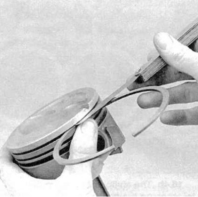
10. Estimate the size of the lateral clearance of the piston rings in their grooves, for which insert a new ring from the outside into its groove on the piston and measure the remaining clearance with a blade-type feeler gauge (see accompanying illustration). Repeat the measurement at two or three points around the groove. Be careful not to mix up the compression rings (the top one is different from the second one). If the gap size exceeds the permissible value (see Specifications), the pistons must be replaced.
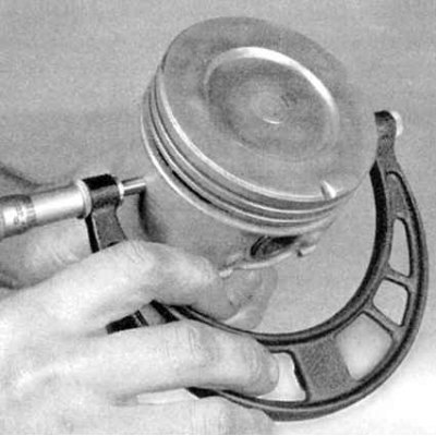
11. Determine the piston clearance in your cylinders by measuring the diameters of the latter (see Checking the condition of the engine block) and subtract the diameters of the corresponding pistons from them. The piston diameter is measured along its skirt, at an angle of 90° (see accompanying illustration) to the axis of the piston pin. 12. If the piston clearance in the cylinder exceeds the permissible value (see Specifications), the block should be given for resurfacing with the selection of new pistons of repair diameter.
13. Assess the correctness of the piston seating on the connecting rods by attempting to rotate the components in opposite directions. The presence of any noticeable play indicates excessive wear of the joint. To correct the situation, the connecting rod and piston assemblies should be delivered to a car service workshop, where the necessary restoration repairs and replacement of the pins will be carried out.
14. Performing the procedure for removing pistons from connecting rods (if such a need arises) should also be entrusted to car service specialists. In parallel, the connecting rods can be checked for signs of bending, twisting and other deformations using special diagnostic equipment.
Note: Do not remove pistons from connecting rods unless necessary.
15. Check the connecting rods for cracks and other mechanical damage. Temporarily remove the lower head caps, remove the old bearing liners, wipe the beds in the caps and heads and check them for burrs, scoring and roughness. After completing the check, put the old liners back in place, install the caps on the lower heads of the connecting rods and tighten the mounting bolts by hand.
Note: If the engine is being rebuilt to eliminate pin knock, replace the connecting rod assemblies.
[Full version on the source website hondabook.ru]