
Disassembly of the connecting rod and piston group
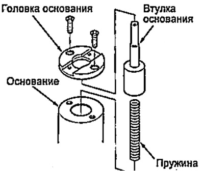
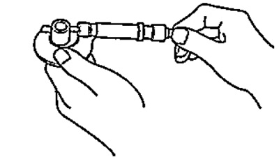
1. Assemble the tool as shown in the figure.
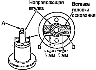
2. Temporarily install the guide bushing on the base bushing (A) and adjust the base head insertion position as shown in the figure, then tighten the screws (IN). Remove the guide bush.
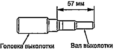
3. Assemble and adjust the length of the drift head and shaft.
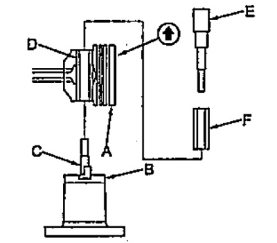
4. Put the piston assembly (A) for a special device (IN) mark on the piston crown up. Make sure the groove on the piston is against the base head insert (WITH), as it shown on the picture.
5. Press out the piston pin (D) drift (E) through the guide (F) using a hydraulic press.
Examination
1. Measure the diameter of the piston pin.
Note: check the parts of the connecting rod and piston group at room temperature.
- Piston pin nominal diameter - 17.996-18.000 mm
2. Set a dial gauge to the piston pin diameter and reset to zero.
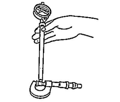
3. Determine the difference between the diameter of the piston bosses and the diameter of the piston pin.
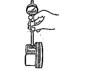
- Nominal clearance between piston bosses and piston pin - 0.010-0.018 mm
4. Measure the inside diameter of the piston head of the connecting rod.
- Nominal diameter - 17.964-17.977 mm
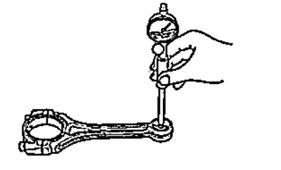
5. Determine the difference between the diameter of the piston head of the connecting rod and the piston pin.
- The clearance between the piston head of the connecting rod and the piston pin is 0.020 - 0.036 mm
Assembly
1. Assemble the piston and connecting rod so that the arrow on the piston and the raised mark on the connecting rod are on the same side.
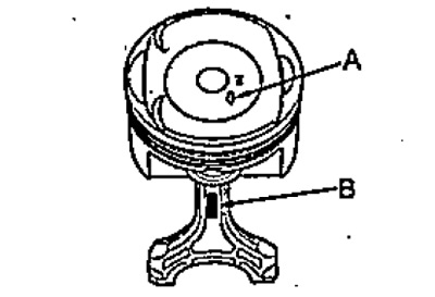
2. Install the guide bush (A) into the piston and connecting rod.
3. Put the piston and connecting rod assembly (B) marks up on the special device (WITH). Make sure the groove on the piston is against the base head insert (D), as it shown on the picture.
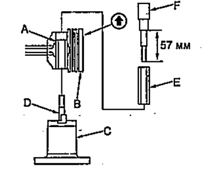
4. Press in the piston pin (E) drift (F) using a hydraulic press.