
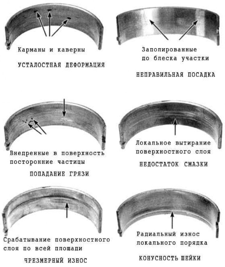
Bearing failure may occur due to lack of lubrication, dirt particles, engine overloads and corrosion. Regardless of the nature of the defects, the cause of damage to the liners must be eliminated during the engine overhaul to avoid recurrence.
For inspection, remove the bearing shells from their beds in the engine block/lower connecting rod heads and main/connecting rod caps and lay them out in the order of installation on a clean work surface. The organized placement of the shells will allow you to link the nature of the detected defects to the condition of the corresponding shaft journals.
Dirt and foreign particles enter the engine in various ways. They can be left inside the block during assembly, or penetrate through filters or the crankcase ventilation system. All particles that enter the engine oil eventually end up in the bearings. Metal filings, formed during the normal operation of internal engine components, are often embedded in the soft material of the bearings. There is a high probability of the presence of traces of abrasive in the bearings, especially when due attention was not paid to cleaning the block after the completion of the engine overhaul. Regardless of the method by which foreign particles enter the engine, they are highly likely to end up embedded in the soft surface of the crankshaft bearing shells and are easily detected during a visual inspection of the latter. Large particles are usually not retained in the bearings, but leave noticeable traces on their surface and the surface of the shaft journals in the form of scratches, cavities and scuffs. The best guarantee against such troubles is a responsible attitude to cleaning components after the completion of a major engine overhaul and careful observance of cleanliness during assembly. Frequent regular changes of engine oil also allow you to significantly extend the service life of bearings.
Oil starvation can be a consequence of several different, but often interrelated phenomena. Thus, engine overheating leads to dilution of the motor oil and its displacement from the working clearances of the bearings. Insufficient lubrication of the bearings can be explained by excessive size of the working clearances, as well as by ordinary leaks (internal or external). A common cause of oil being forced out of bearing gaps is constant overspeeding of the engine (usually associated with improper alignment of holes when installing components) also leads to a reduction in the supply of lubricant to the bearings. A typical result of oil starvation is complete or local wiping/tearing of the surface layer of the bearings from the metal substrate. In this case, the operating temperature can rise to such a level that the substrate acquires a bluish tint as a result of overheating.
The driving style of the car owner also has a significant impact on the service life of bearings. Driving at low speed in high gear leads to significant overloads of the bearings, accompanied by the displacement of the oil film from their working gaps. This type of overload leads to increased plasticity of the liners and the occurrence of cracks in the surface layer (fatigue deformation). In this case, the surface material begins to crumble and separate from the steel substrate. Car operation in the urban cycle (frequent short distance travel) leads to the development of bearing corrosion due to the fact that insufficient engine heating leads to condensation and the release of chemically aggressive gases. These products accumulate in engine oil, forming slags and acids. When such oil gets into bearings, aggressive substances contribute to the development of liners corrosion.
Incorrect installation of liners during engine assembly can also cause their rapid destruction. Too tight a fit does not provide the required working clearance of the bearings, which leads to their oil starvation. The result of foreign particles getting under the liners during installation is the formation of elevations, the surface layer of which is quickly wiped off.
Selection of inserts
In case of wear or damage to the main bearing shells, and also when it is not possible to achieve the correct value of the working clearance (see Installing the crankshaft and checking the main bearing clearances or Installation of connecting rod and piston assemblies and checking the size of working clearances in the connecting rod bearings of the crankshaft), the situation can be corrected in the manner described below, by selecting and installing new liners. If the crankshaft has been machined, it must be equipped with liners of the corresponding repair (with disparagement) sizes – usually the selection of liners is carried out by the specialists who performed the turning of the shaft journals. Regardless of the method for determining the required size of the liners, the working clearances of the bearings must then be checked using the Plastigage measuring kit (see below).
Note: If the working clearances cannot be adjusted properly by selecting liners, the shaft must be replaced.
Main bearings
1. If you need to select new STANDARD size liners, select one that has the same color markings as the old one.
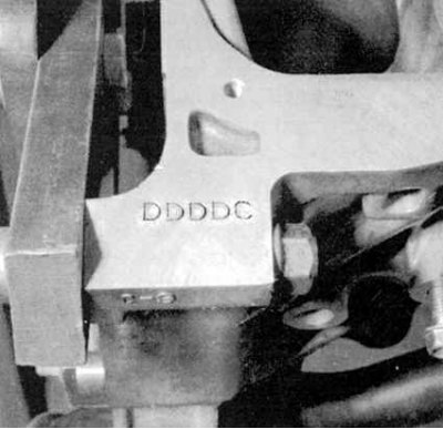
2. If the color markings on the old bearing are missing, locate the markings stamped on the block for the main bearing journals (see accompanying illustration).
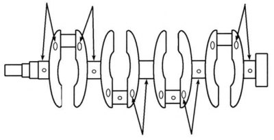
3. Also check the class marking of the main bearings on the shaft itself (see accompanying illustration). 4. When selecting new inserts, use the color-coded identification card (see below).
| A | B | C | D | |
| 1 | RED | PINK | YELLOW | GREEN |
| 2 | PINK | YELLOW | GREEN | BROWN |
| 3 | YELLOW | GREEN | BROWN | BLACK |
| 4 | GREEN | BROWN | BLACK | BLUE |
Connecting rod bearings
1. When selecting new STANDARD size inserts, also use the color marking.
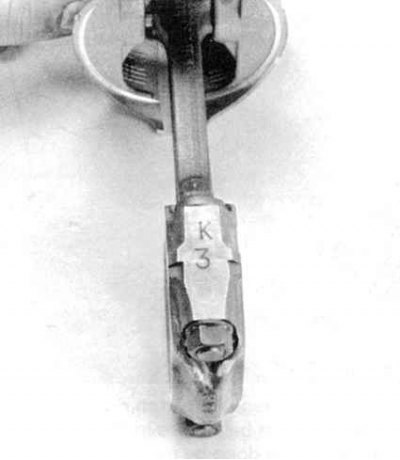
2. If the color code on the old bearings has been lost, look for the markings on the lower heads of the connecting rods (see accompanying illustration). The number mark characterizes the size class of the connecting rod bearing (it should not be confused with the cylinder number).
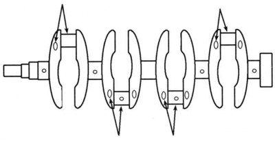
3. Also check the letter marks on the shaft itself (see accompanying illustration).
4. When selecting new inserts, use the color-coded identification card (see below).
| A | B | C | D | |
| A or I | RED | PINK | YELLOW | GREEN |
| B or II | PINK | YELLOW | GREEN | BROWN |
| C or III | YELLOW | GREEN | BROWN | BLACK |
| D or III | GREEN | BROWN | BLACK | BLUE |
All bearings
Remember that the final parameter determining the correctness of the selection of liners is the result of measuring the working clearances in the bearings. Feel free to contact the representatives of the Honda branded service center with any questions.
The text of the article is available on the website HONDABOOK