


Car heater and air conditioner Honda Fit/Jazz 1

Safety precautions when working with refrigerant
Always follow safety precautions when working with refrigerant. 1. Do not work with refrigerant in a closed room or near an open flame. 2. Always wear safety glasses. 3. Avoid contact with skin, eyes or mouth. In case...
Always follow safety precautions when working with refrigerant. 1. Do not work with refrigerant in a closed room or near an open flame. 2. Always wear safety glasses. 3. Avoid contact with skin, eyes or mouth. In case...

Location of heating system components
Component Locations (Right Hand Drive Models). 1 - heater fan motor relay, 2 - condenser fan motor relay, cooling system fan motor relay, air conditioning compressor electromagnetic clutch relay, 3 - noise suppressor, 4...
Component Locations (Right Hand Drive Models). 1 - heater fan motor relay, 2 - condenser fan motor relay, cooling system fan motor relay, air conditioning compressor electromagnetic clutch relay, 3 - noise suppressor, 4...

Checking the Heater Fan Motor Circuit (Right Hand Drive Models)
1. Check fuse #5 (40A) of the relay unit. If the fuse is faulty, it should be replaced; if it is OK, proceed to step #2. 2. Remove and check the relay of the electric motor of the heater fan. If the relay is working...
1. Check fuse #5 (40A) of the relay unit. If the fuse is faulty, it should be replaced; if it is OK, proceed to step #2. 2. Remove and check the relay of the electric motor of the heater fan. If the relay is working...

Vacuuming, charging and checking the system
Attention: If a refrigerant leak occurs, ventilate the room before recharging the system. Additional information on safe handling of refrigerant and compressor oil can be obtained from the instructions for use. When...
Attention: If a refrigerant leak occurs, ventilate the room before recharging the system. Additional information on safe handling of refrigerant and compressor oil can be obtained from the instructions for use. When...

Checking the Heater Fan Motor Circuit (Left Hand Drive Models)
1. Turn the ignition key to the "ON" position and turn on the heater fan. If the rotation speed of the heater fan motor changes in accordance with the set modes of the rotation speed switch, then continue checking from...
1. Turn the ignition key to the "ON" position and turn on the heater fan. If the rotation speed of the heater fan motor changes in accordance with the set modes of the rotation speed switch, then continue checking from...
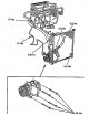
Tightening torques for threaded connections of the air conditioning system
Tightening torques for threaded connections of the air conditioning system (right-hand drive models). Tightening torques for threaded connections of the air conditioning system (left-hand drive models).
Tightening torques for threaded connections of the air conditioning system (right-hand drive models). Tightening torques for threaded connections of the air conditioning system (left-hand drive models).

Checking the Condenser Fan Circuit (Right Hand Drive Models)
1. Remove the condenser fan motor relay from the relay box and test it. If the relay is faulty, replace it; if the relay is OK, proceed to step #2. 2. Measure the voltage between terminal "2" of the condenser fan motor...
1. Remove the condenser fan motor relay from the relay box and test it. If the relay is faulty, replace it; if the relay is OK, proceed to step #2. 2. Measure the voltage between terminal "2" of the condenser fan motor...

Checking the Condenser Fan Circuit (Left Hand Drive Models)
Note: Do not use this troubleshooting algorithm if the fan does not work even with the air conditioner on. 1. Check fuse #11 (30 A) of the relay box and fuse #10 (7.5 A) of the fuse box. If the fuses are faulty, they...
Note: Do not use this troubleshooting algorithm if the fan does not work even with the air conditioner on. 1. Check fuse #11 (30 A) of the relay box and fuse #10 (7.5 A) of the fuse box. If the fuses are faulty, they...

Checking the common circuit of the radiator and condenser fans
Right hand drive models 1. Turn off the air conditioner. Turn the ignition key to the "ON" position. 2. Check the voltage between terminal "6" of the ECU connector and ground. If the voltage matches the battery voltage,...
Right hand drive models 1. Turn off the air conditioner. Turn the ignition key to the "ON" position. 2. Check the voltage between terminal "6" of the ECU connector and ground. If the voltage matches the battery voltage,...

Checking the Radiator Fan Circuit (Right Hand Drive Models)
1. Check fuse No.10 (20 A) of the relay block, if the fuse is faulty, it should be replaced, if it is good; proceed to point #2. 2. Remove and check the cooling system fan motor relay. If the relay is OK, proceed to...
1. Check fuse No.10 (20 A) of the relay block, if the fuse is faulty, it should be replaced, if it is good; proceed to point #2. 2. Remove and check the cooling system fan motor relay. If the relay is OK, proceed to...

Checking the Heater Fan Speed Switch Circuit (Right Hand Drive Models)
1. Disconnect the heater fan motor connector. 2. Disconnect the heater blower resistor connector. 3. Disconnect the heater fan speed switch connector. 4. Check the conductivity between the ground and terminals "1", "2",...
1. Disconnect the heater fan motor connector. 2. Disconnect the heater blower resistor connector. 3. Disconnect the heater fan speed switch connector. 4. Check the conductivity between the ground and terminals "1", "2",...

Checking the air conditioning system circuits (right-hand drive models)
1. Disconnect the pressure switch connector. 2. Turn the ignition key to the "ON" position. 3. Measure the voltage between terminal "2" of the pressure switch connector and ground. If the voltage is 4.30-5.25 V, proceed...
1. Disconnect the pressure switch connector. 2. Turn the ignition key to the "ON" position. 3. Measure the voltage between terminal "2" of the pressure switch connector and ground. If the voltage is 4.30-5.25 V, proceed...

Checking the air conditioning system circuits (left-hand drive models)
1. Disconnect the electromagnetic clutch connector. 2. Turn the ignition key to the "ON" position. 3. Measure the voltage between terminal No.3 of the electromagnetic clutch connector and ground. If the voltage is...
1. Disconnect the electromagnetic clutch connector. 2. Turn the ignition key to the "ON" position. 3. Measure the voltage between terminal No.3 of the electromagnetic clutch connector and ground. If the voltage is...

Checking the electromagnetic clutch circuit (right-hand drive models)
1. Check the electromagnetic clutch relay. If the relay is OK, proceed to step #2, if it is faulty, it should be replaced. 2. Measure the voltage between terminal "2" of the electromagnetic clutch relay connector and...
1. Check the electromagnetic clutch relay. If the relay is OK, proceed to step #2, if it is faulty, it should be replaced. 2. Measure the voltage between terminal "2" of the electromagnetic clutch relay connector and...

Checking the electromagnetic clutch circuit (left-hand drive models)
1. Check fuse #11 (30 A) of the relay box and fuse #10 (7.5 A) of the fuse box. If the fuses are OK, proceed to step #2, if the fuses are bad, replace them and repeat the check. 2. Connect the diagnostic tester to the...
1. Check fuse #11 (30 A) of the relay box and fuse #10 (7.5 A) of the fuse box. If the fuses are OK, proceed to step #2, if the fuses are bad, replace them and repeat the check. 2. Connect the diagnostic tester to the...

Heater Fan Unit — Removal and Installation
Note: Install in the reverse order of removal, after installation, make sure there are no air leaks. 1. Remove the instrument panel. 2. Disconnect the air intake flap drive cable. 3. Disconnect the electric motor...
Note: Install in the reverse order of removal, after installation, make sure there are no air leaks. 1. Remove the instrument panel. 2. Disconnect the air intake flap drive cable. 3. Disconnect the electric motor...

Replacing the Heater Fan Unit Components
The heater blower motor and filter can be replaced without removing the heater blower assembly. The heater motor is secured with three screws as shown in the figure. 1 - heater fan electric motor assembled with fan, 2 -...
The heater blower motor and filter can be replaced without removing the heater blower assembly. The heater motor is secured with three screws as shown in the figure. 1 - heater fan electric motor assembled with fan, 2 -...

Air conditioning and heating unit — removal and disassembly
Note: Please read the chapter before removing " Safety system (SRS) ". Installation is carried out in the reverse order of removal. Assembly is carried out in the reverse order of disassembly. When installing, do not...
Note: Please read the chapter before removing " Safety system (SRS) ". Installation is carried out in the reverse order of removal. Assembly is carried out in the reverse order of disassembly. When installing, do not...

Adjusting the air flow mixing flap drive cable
1. Release the lock (1), disconnect the cable (2) from the air flow mixing flap drive lever (3). Right hand drive models. Left-hand drive models. 2. Set the temperature mode switching knob to the "Max Cool" position. 3....
1. Release the lock (1), disconnect the cable (2) from the air flow mixing flap drive lever (3). Right hand drive models. Left-hand drive models. 2. Set the temperature mode switching knob to the "Max Cool" position. 3....

Adjusting the air flow direction flap drive cable
1. Release the lock (1), disconnect the cable (2) from the air flow direction flap drive (3). Right hand drive models. Left-hand drive models. 2. Set the air flow direction switch to the "Vent" position. 3. Turn the air...
1. Release the lock (1), disconnect the cable (2) from the air flow direction flap drive (3). Right hand drive models. Left-hand drive models. 2. Set the air flow direction switch to the "Vent" position. 3. Turn the air...

Adjusting the air intake flap drive cable
1. Release the lock (1), disconnect the cable (2) from the air intake flap drive (3). Right hand drive models. Left-hand drive models. 2. Turn on recirculation. 3. Turn the air intake flap drive lever to the...
1. Release the lock (1), disconnect the cable (2) from the air intake flap drive (3). Right hand drive models. Left-hand drive models. 2. Turn on recirculation. 3. Turn the air intake flap drive lever to the...

Air Conditioning Compressor — Removal and Installation
Note: Installation is carried out in the reverse order of removal. Replace all O-rings with new ones before installation. Never mix or reuse used compressor oil as this may result in contamination of the system. Never...
Note: Installation is carried out in the reverse order of removal. Replace all O-rings with new ones before installation. Never mix or reuse used compressor oil as this may result in contamination of the system. Never...

Electromagnetic clutch — check
1. Make sure the pressure plate is not damaged. 2. Rotate the pulley by hand to make sure it rotates without difficulty or extraneous noise. 3. Measure the clearance between the pressure plate and the pulley using a...
1. Make sure the pressure plate is not damaged. 2. Rotate the pulley by hand to make sure it rotates without difficulty or extraneous noise. 3. Measure the clearance between the pressure plate and the pulley using a...
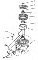
Electromagnetic clutch — disassembly and assembly
Note: Assembly is carried out in the reverse order of disassembly. 1. Using a special tool, fix the pressure plate and unscrew the central nut. Tightening torque: left-hand drive models - 26 Nm right hand drive models -...
Note: Assembly is carried out in the reverse order of disassembly. 1. Using a special tool, fix the pressure plate and unscrew the central nut. Tightening torque: left-hand drive models - 26 Nm right hand drive models -...

Removal and installation the electromagnetic clutch thermal fuse
Note: Installation is carried out in the reverse order of removal. 1. Disconnect the connectors. Left-hand drive models. 1 - wire retainer from the coupling winding, 2 - connector of the clutch winding wire, 3 - thermal...
Note: Installation is carried out in the reverse order of removal. 1. Disconnect the connectors. Left-hand drive models. 1 - wire retainer from the coupling winding, 2 - connector of the clutch winding wire, 3 - thermal...

Removal and installation the air conditioner condenser
Note: Installation is carried out in the reverse order of removal. 1. Remove the refrigerant from the system. 2. Remove the front bumper. 3. Loosen the bolt and nut and disconnect the condenser inlet and outlet pipes....
Note: Installation is carried out in the reverse order of removal. 1. Remove the refrigerant from the system. 2. Remove the front bumper. 3. Loosen the bolt and nut and disconnect the condenser inlet and outlet pipes....

Removal and installation the air conditioner condenser dryer
Note: Installation is carried out in the reverse order of removal. 1. Remove the capacitor. 2. Remove the support, unscrew the cover, remove the sealing rings, filter and dehydrator. 1 - support, 2 - cover, 3 - sealing...
Note: Installation is carried out in the reverse order of removal. 1. Remove the capacitor. 2. Remove the support, unscrew the cover, remove the sealing rings, filter and dehydrator. 1 - support, 2 - cover, 3 - sealing...

Evaporator — removal and installation
Note: Installation is carried out in the reverse order of removal. When installing a new evaporator, pour a small amount of compressor oil into it. When installing, make sure the evaporator plate is installed in the...
Note: Installation is carried out in the reverse order of removal. When installing a new evaporator, pour a small amount of compressor oil into it. When installing, make sure the evaporator plate is installed in the...

Air filter — removal and installation
Note: Installation is carried out in the reverse order of removal. Canadian (DX) models are not equipped with an air filter. 1. Remove the glove box. 2. Remove the filter holder assembly with the air filter. 3. Remove...
Note: Installation is carried out in the reverse order of removal. Canadian (DX) models are not equipped with an air filter. 1. Remove the glove box. 2. Remove the filter holder assembly with the air filter. 3. Remove...

Air Conditioner and Heater Control Panel — Removal and Installation
Left hand drive models Note: Installation is carried out in the reverse order of removal. After installation, adjust the damper drive cables. After installation, make sure the switches are working properly. 1. Remove...
Left hand drive models Note: Installation is carried out in the reverse order of removal. After installation, adjust the damper drive cables. After installation, make sure the switches are working properly. 1. Remove...

Air Conditioner and Heater Control Panel — Disassembly and Assembly
Note: Assembly is carried out in the reverse order of disassembly. 1. Remove the air conditioning and heating control panel. 2. Remove the heater fan speed switch (see Fig. "Disassembling and assembling the air...
Note: Assembly is carried out in the reverse order of disassembly. 1. Remove the air conditioning and heating control panel. 2. Remove the heater fan speed switch (see Fig. "Disassembling and assembling the air...

Checking the air flow direction switch
1. Remove the air conditioning and heating control panel. 2. Check the conductivity between terminals "3" and "4" of the air flow direction switch connector when turning the handle from position "1" to position "2". 3....
1. Remove the air conditioning and heating control panel. 2. Check the conductivity between terminals "3" and "4" of the air flow direction switch connector when turning the handle from position "1" to position "2". 3....

Checking the heater fan speed switch
Make sure that the conductivity between the terminals of the heater fan speed switch connector corresponds to the data given in the table.
Make sure that the conductivity between the terminals of the heater fan speed switch connector corresponds to the data given in the table.

Air Conditioner Switch — Removal and Installation
Note: Installation is carried out in the reverse order of removal. 1. Remove the center trim. 2. Disconnect the connector and remove the switch. Left-hand drive models. 1 - connector, 2 - air conditioning switch and...
Note: Installation is carried out in the reverse order of removal. 1. Remove the center trim. 2. Disconnect the connector and remove the switch. Left-hand drive models. 1 - connector, 2 - air conditioning switch and...

Air Conditioner Switch — Check
1. Check for conductivity between the terminals according to the table below. Table. Left-hand drive models. Table. Right-hand drive models. 2. If the conductivity is not correct, replace the bulbs or the air...
1. Check for conductivity between the terminals according to the table below. Table. Left-hand drive models. Table. Right-hand drive models. 2. If the conductivity is not correct, replace the bulbs or the air...

Diagnostics of air conditioner with automatic control
1. Remove the lower center trim cover. 2. Turn the ignition "ON" and read the fault codes by the number of flashes of the indicator of the electronic control unit of the air conditioner and heater. Note: If there are...
1. Remove the lower center trim cover. 2. Turn the ignition "ON" and read the fault codes by the number of flashes of the indicator of the electronic control unit of the air conditioner and heater. Note: If there are...

Checking the Heater Fan Resistor (Manual Air Conditioner)
1. Remove the instrument panel. 2. Disconnect the heater fan resistor connector. 3. Check the resistance between the terminals of the heater fan resistor connector. 4. If the resistances do not correspond to those given...
1. Remove the instrument panel. 2. Disconnect the heater fan resistor connector. 3. Check the resistance between the terminals of the heater fan resistor connector. 4. If the resistances do not correspond to those given...

Checking the temperature sensor behind the evaporator
1. Place the temperature sensor behind the evaporator in a container of cold water and measure the resistance between the sensor terminals. 2. Gradually add hot water to the container and make sure that the resistance...
1. Place the temperature sensor behind the evaporator in a container of cold water and measure the resistance between the sensor terminals. 2. Gradually add hot water to the container and make sure that the resistance...


Removal and installation the cabin air temperature sensor (air conditioning with automatic control)
Note: Installation is carried out in the reverse order of removal. 1. Remove the instrument cluster. 2. Disconnect the air hose (A) and connector (B). Loosen the screws and remove the sensor (C).
Note: Installation is carried out in the reverse order of removal. 1. Remove the instrument cluster. 2. Disconnect the air hose (A) and connector (B). Loosen the screws and remove the sensor (C).

Removal and installation the ambient air temperature sensor (air conditioning with automatic control)
Note: Installation is carried out in the reverse order of removal. Remove the sensor as shown in the figure.
Note: Installation is carried out in the reverse order of removal. Remove the sensor as shown in the figure.

Checking the cabin air temperature sensor and the ambient air temperature sensor (air conditioning with automatic control)
1. Check the change in resistance between the terminals of the sensor connector depending on the change in temperature. Interior air temperature sensor. Ambient air temperature sensor. 2. If the resistance change does...
1. Check the change in resistance between the terminals of the sensor connector depending on the change in temperature. Interior air temperature sensor. Ambient air temperature sensor. 2. If the resistance change does...

Removal and installation the sun sensor (air conditioning with automatic control)
Note: Installation is carried out in the reverse order of removal. Remove the sensor from the instrument panel and disconnect the connector.
Note: Installation is carried out in the reverse order of removal. Remove the sensor from the instrument panel and disconnect the connector.

Checking the Sunlight Sensor (Automatic Air Conditioner)
1. Turn on the ignition ("ON"). 2. Check the voltage between terminals "1" ("+") and "2" ("-") of the sensor connector under different lighting conditions. Voltage: sensor not illuminated - 3.6 - 3.7 V sensor...
1. Turn on the ignition ("ON"). 2. Check the voltage between terminals "1" ("+") and "2" ("-") of the sensor connector under different lighting conditions. Voltage: sensor not illuminated - 3.6 - 3.7 V sensor...

Removal and installation the air flow mixing flap drive (air conditioning with automatic control)
Note: Installation is carried out in the reverse order of removal. 1. Remove the lower instrument panel trim on the passenger side. 2. Disconnect the connector (A), loosen the screws and remove the air mixing flap...
Note: Installation is carried out in the reverse order of removal. 1. Remove the lower instrument panel trim on the passenger side. 2. Disconnect the connector (A), loosen the screws and remove the air mixing flap...

Checking the air flow mixing flap drive (air conditioning with automatic control)
1. Disconnect the air mixing flap actuator connector. 2. Connect the positive terminal of the battery to terminal "1" of the actuator connector, and the negative terminal to terminal "2" and make sure that the actuator...
1. Disconnect the air mixing flap actuator connector. 2. Connect the positive terminal of the battery to terminal "1" of the actuator connector, and the negative terminal to terminal "2" and make sure that the actuator...

Removal and installation the air flow direction flap actuator (air conditioning with automatic control)
Note: Installation is carried out in the reverse order of removal. 1. Remove the glove box. 2. Disconnect the connector (A), loosen the mounting screws and remove the air flow direction flap actuator (B).
Note: Installation is carried out in the reverse order of removal. 1. Remove the glove box. 2. Disconnect the connector (A), loosen the mounting screws and remove the air flow direction flap actuator (B).

Checking the air flow direction flap actuator (air conditioning with automatic control)
1. Disconnect the damper actuator connector. 2. Connect the positive battery terminal to terminal "1" of the actuator connector and the negative battery terminal to terminal "2" and check that the actuator operates in...
1. Disconnect the damper actuator connector. 2. Connect the positive battery terminal to terminal "1" of the actuator connector and the negative battery terminal to terminal "2" and check that the actuator operates in...

Checking the power transistor (air conditioner with automatic control)
1. Remove the lower instrument panel trim on the passenger side. 2. Disconnect the power transistor connector. 3. Check the resistance between terminals "3" and "4" of the power transistor. Nominal resistance - 1.5 kOhm...
1. Remove the lower instrument panel trim on the passenger side. 2. Disconnect the power transistor connector. 3. Check the resistance between terminals "3" and "4" of the power transistor. Nominal resistance - 1.5 kOhm...

Self-diagnosis (additions for right-hand drive models from 06.2004)
1. Turn the ignition "ON". 2. Press the "AUTO" switch and, without releasing it, press the "OFF" switch on the air conditioning and heating control panel. 3. Determine the malfunction by turning on the temperature...
1. Turn the ignition "ON". 2. Press the "AUTO" switch and, without releasing it, press the "OFF" switch on the air conditioning and heating control panel. 3. Determine the malfunction by turning on the temperature...
This section is available on: russian, bulgarian, belarusian, ukrainian, serbian, croatian, romanian, polish, slovak, hungarian
Link in different formats to this section
TEXTHTMLBB Code
- General information
- User manual
- Maintenance
- Power unit
- Engine repair
- Cooling and lubrication system
- Injection and power system
- Control system
- Engine electrical equipment
- Transmission
- Clutch
- Mechanical gearbox
- Automatic gearbox
- Variator (CVT)
- Drive shafts and gearbox
- Chassis and running gear
- Car suspension
- Steering
- Brake system
- Body and interior
- Exterior (external elements)
- Interior (internal elements)
- Doors, locks and windows
- Heater and air conditioner
- Safety system
- Electrical equipment
- Equipment and devices
- Wiring diagrams (since 06.2001)
- Wiring diagrams (since 06.2004)