
Withdrawal
1. Remove the cylinder head cover (see Section 4), drive belt and toothed pulley (see Section 7).
2. Remove the ignition distributor (see chapter 5).
3. Loosen the lock nuts of the adjusting bolts and by unscrewing them, close all valves (see chapter 1). Measure the camshaft end play with a dial gauge. If the gap is out of range, then the camshaft or cylinder head should be replaced or the necessary play should be provided with special washers - spacers.
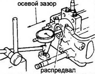
Pic. 10.3 Checking the axial clearance of the camshaft using an indicator. Move the shaft back and forth as shown by the arrows
4. Loosen the rocker axle post bolts about ¼ turn in a criss-cross pattern. Once all bolts are loose, remove the rocker shaft assembly.
Leave the rack mounting bolts in their holes to avoid disassembly of the assembly under the action of the remote springs.
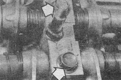
Pic. 10.4 Loosen the bolts of the rack axles of the rocker arms (arrows)
5. Remove the camshaft and wash it.
Inspection
6. Visually assess the condition of the cams and camshaft journals. Check for wear, pitting, chafing, metal build-up and signs of overheating (discolorations, discolored areas). Determine the presence of peeling of the hard layer of the surface of each cam.
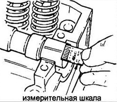
7. Using a micrometer, measure the height of each cam.
If the measured cam height is less than the specified value, replace the camshaft.
8. Determine the clearances in the camshaft bearings in the following order:
- A) wash the bearing caps and shaft journals in gasoline or diesel fuel and wipe dry.
- b) carefully insert the shaft into the bed of the head. Do not rotate the shaft during measurements.
- V) put pieces of plastic gauge on each shaft journal.
- G) reinstall the rocker axle assembly and hand-tighten the strut bolts.
- d) tighten the bolts to specification in ¼ turn increments in the sequence shown in fig. 10.8a.
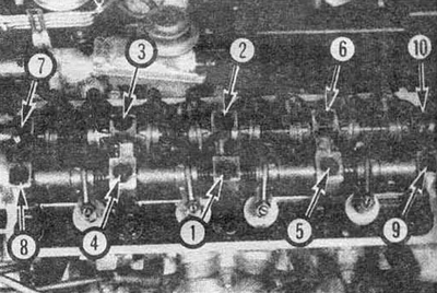
Pic. 10.8а The sequence of tightening the bolts of the racks of the rocker axles
Pic. 10.8b Comparison of the width of the crushed gauges with a scale for determining the clearance in the bearing
- e) unscrew the bolts as indicated in point 4 and remove the rocker axle assembly.
- and) compare the thickness of the crushed calibers (8 widest point) with a scale on the envelope with gauges (see fig. 10.86).
- h) if the measured clearance is greater than the allowable value, the camshaft and/or cylinder head must be replaced.
- And) scrape off the remaining plastic gauges from the shaft journals.
9. Take out bolts of fastening of racks of yokes and remove details from axes of yokes. Store the parts in the same order they were on the axle.
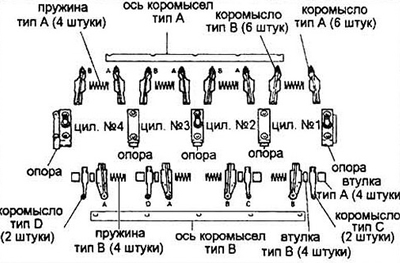
Pic. 10.9 Assembling the rocker shaft assembly (carbureted engines)
10. Visually determine the presence of wear on the ends of the rocker arms and their bearings. Determine the condition of the adjusting screws and locknuts, bearing cap surfaces, springs and bushings.
11. Using a micrometer, determine the diameter of the axes of the rocker arms in the places where the rocker arms work.
12. Measure the inside diameter of the rocker arm bearings. Based on the measurement results, determine the clearances in the respective bearings.
13. If clearances are greater than allowable, replace worn parts.
Installation
14. Collect an axis of yokes and insert bolts into holes of racks for prevention of spontaneous dismantling. All mating surfaces and oil supply holes must be clean and lubricated with engine oil.
15. Lay the camshaft in the bed of the cylinder head so that the keyway looks up.
16. Install the camshaft oil seal (if necessary see Section 9), by lubricating the edges with engine oil.
17. Install the rocker axle assembly and hand-tighten the strut bolts
18. Bolts of fastening of racks tighten steps on ¼ of a turn in the sequence specified in fig. 10.8a up to the force described in the specification.
19. Install the key and insert the camshaft drive gear pulley. Tighten the toothed pulley mounting bolt to specification. To prevent the shaft from rotating, insert a large screwdriver or wrench into the hole in the toothed pulley. Make sure. that the timing marks on the toothed pulley are correctly aligned with the cylinder head (see figure 7.22).
20. Install the drive belt and the removed units in the reverse order of removal.