Contents: Hand check ⇊ Checking with special tools ⇊
Hand check
1. Remove the valve cover.
- For valve cover installation, see below.
2. Press your finger on the center intake rocker arm (for high speed) of the intake valve and make sure that it moves independently of the primary and secondary rocker arms.
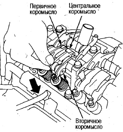
Caution: Perform the above check on each cylinder, setting each piston to the TDC position on the compression stroke.
- Replace the intake rocker arm assembly if necessary.
Checking with special tools
Before checking/using a special tool, check for independent movement of the central rocker arm (see above).
Checking with a special tool is performed in the following cases:
- During disassembly of the cylinder head.
- When the power at high revs has significantly decreased, and diagnostics do not reveal the cause of the malfunction.
Caution: During the test, the pressure in the special tool (as indicated by the pressure gauge) must be maintained above 250 kPa (2.5 kg/cm²), so please follow the conditions listed below.
1) Turn on the compressor and use the pressure gauge to make sure that the required pressure has been established in the tank.
2) Connect the air supply as close to the compressor outlet as possible.
3) Perform the test in the shortest possible time. If the test is performed slowly (over 6 seconds), the pressure may drop and the high-speed rocker arm will not engage.
- The test is performed on each cylinder at the TDC position of the compression stroke.
- Before checking, make sure the valve clearances are normal.
- Cover the timing belt with a rag.
- When pressurizing, oil may splash out through the hole, so increase the pressure smoothly by operating the adjusting valve of the special tool.
1. Remove the valve cover.
- For valve cover installation, see below.
2. Install the air shut-off pliers (special tool) into the bypass valve hole.
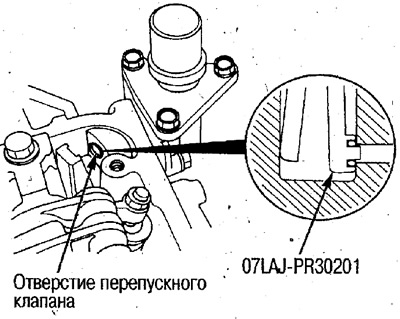
3. Unscrew the plug from the cylinder head inspection hole and install the special tool. Wipe off the oil flowing out of the inspection hole with a rag.
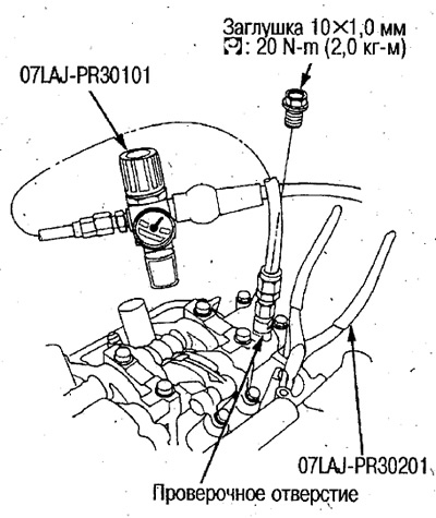
4. Build up the required pressure and make sure the high speed rocker arm engages.
Standard pressure: 250-490 kPa (2.5-5.0 kg/cm²)
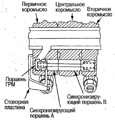
5. After applying pressure, lift the locking plate slightly (2-3 mm) to move the synchronizing pistons. Make sure visually and by clicking that all 3 rocker arms (primary, central and secondary) are engaged.
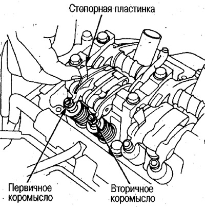
- The synchronizing pistons should be visible through the gaps between the primary, central and secondary rocker arms.
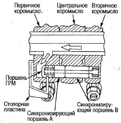
- The locking plate fits into a groove inside the timing piston and the synchronizing pistons are fixed (Fig. top right).
6. Press your finger on the center rocker arm and make sure all 3 intake rocker arms are engaged with the timing pistons and do not move.
 |
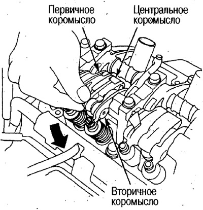 |
- If the rocker arms do not operate satisfactorily, replace the intake valve rocker arm assembly.
7. Release the pressure, lift the locking plate slightly and visually check that the synchronizing pistons have returned to their original position.
- When the plate is lifted, it comes out of the groove of the timing piston and, under the action of the spring, the synchronizing pistons return to their original position.
- If the rocker arms do not operate satisfactorily, replace the intake valve rocker arm assembly.
8. Remove the special tool, press the center rocker arm with your finger and check the operation of the rocker arm assembly. Make sure that when pressed lightly, the rocker arm moves down slightly, and when pressed hard, it moves down deeply.
- If the rocker arm movement is not smooth, replace the rocker arm assembly.
9. After completing the work, make sure that the self-diagnosis lamp (PCM-FI indicator lamp) does not light.