
General description
1. The intake air temperature control system ensures air heating during engine warm-up and maintains the intake temperature at about 40 degrees Celsius. This improves the conditions for the carburetor to create the optimum fuel-air mixture.
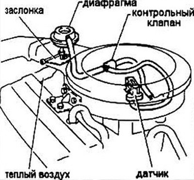
Fig. 11.1 Schematic diagram of the intake air temperature control system
2. The balance between the amount of warm and cold air is ensured by a damper in the air filter housing, controlled by a diaphragm.
3. Warm air is taken from under the casing covering the exhaust manifold. When the engine reaches a sufficient temperature, the sensor sends a signal to the control valve, which opens the vacuum access to the diaphragm, and the flap switches the air intake location.
Control
Note: the test is carried out on a cold, switched-off engine.
4. Check the integrity of all vacuum hoses serving the diaphragm.
5. Set the car's parking brake and block the wheels.
6. Disconnect, but do not remove, the air filter housing (see Chapter 4).
7. Turn the air filter housing so that the flap is visible. It should be open. Otherwise, check for jamming of the flap. Move the flap by hand and make sure there is no deviation.
8. If the throttle moves freely and the vacuum control is insufficient, carefully inspect the vacuum hoses for leaks. If no leaks are found, replace the diaphragm.
Replacement of system elements
9. Remove the diaphragm by turning it 90 degrees.
10. Installation is performed in the reverse order of removal. Make sure that the diaphragm rod engages with the valve.
[Refer to the original source on the website www.hondabook.ru]