
2. On engine models with carburetors, the EGR system consists of a bypass valve, two control valves and a thermal valve. The bypass valve is actuated by vacuum passing through the two control valves and bypasses the exhaust gas depending on the engine load. To eliminate recirculation at idle, the vacuum is taken from above the throttle valve. When the engine is cold, the thermal valve is open and relieves the vacuum from the bypass valve, thus there is no bypass during warm-up. When the engine reaches the operating temperature of the thermal valve, the latter closes and the bypass valve is controlled by valve A. Valve 8 is normally closed. When a certain vacuum in the intake manifold is reached, the control is carried out by valves A and B.
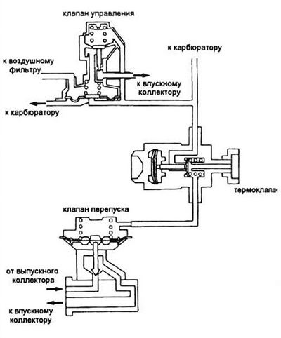
Pic. 16.2. Diagram of the exhaust gas recirculation system
3. On injection engine models, the EGR system consists of bypass valve, control solenoid valve, EMU and various sensors. The EMU memory contains a bypass valve lift control program for all operating conditions.
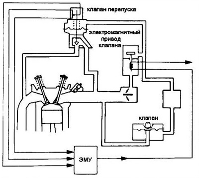
Pic. 16.3 Typical EGR system for injection engines
Control
Bypass valve
4. Start the engine. Leave it idle.
5. Disconnect the vacuum hose from the valve and connect the vacuum pump in its place.
6. Apply vacuum to the valve. The discharge should be stable, and the engine should work poorly at this time.
- A) if the vacuum is unstable and the engine does not react in any way, replace the bypass valve;
- b) if the vacuum is stable and the engine is running smoothly, remove the valve and check it is closed. Clean the passage holes from carbon deposits.
ROG system (carburetor)
7. Disconnect the vacuum hose from the bypass valve and connect a vacuum gauge.
8. Start the engine and warm it up until the cooling fan turns on.
9. Remove the control box on the rear wall of the engine compartment (four bolt mounting), then remove the cover (four screws). There must be a vacuum in the valve hose.
- A) no vacuum at idle. If so, check that the vacuum hoses are properly connected (table under the hood) or replace the bypass valve;
- b) at 4500 rpm there should be a vacuum of 2 to 6 mm Hg. Art. If not, check thermostatic valve connections (entrance and exit). If there is vacuum at the inlet but not at the outlet, replace the thermoclalan. If there is no vacuum at the inlet, check the hoses;
- V) at 4500 rpm with a pinched vacuum release hose, the vacuum should not be more than 2 mm Hg. Art. Replace the valve and check that the hoses are properly connected.
- G) during rapid acceleration, the vacuum should be in the range of 2-6 mm Hg. Art. If this is not. check the vacuum at the inlet and outlet of the thermal valve. If there is a vacuum at the inlet, but not at the outlet, replace the thermal valve. If there is no vacuum at the inlet, check the hoses.
- d) there must be no vacuum during deceleration.