
Attention: when replacing the pads, change the return and support springs - over time, under the influence of multiple heating/cooling cycles, they lose their original qualities.
1. Loosen the wheel nuts, raise the rear of the car. Place it on stands. Block the front wheels. Remove the rear wheels and release the parking brake.
2. Remove the brake drum. If the drum does not come off, tap it lightly and screw a couple of M8 bolts into the special threaded holes. If the drum does not come off in this case, it means that the shoes have made quite deep grooves in the drum. Remove the rubber plug in the support disk and use a screwdriver to turn the automatic adjustment mechanism adjustment nuts until the drum comes off.
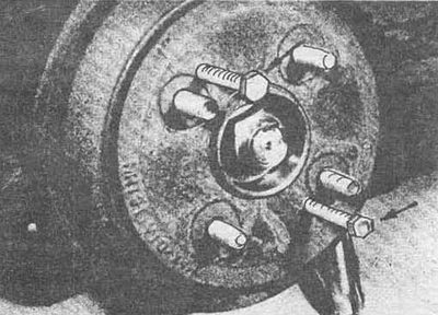
Fig. 5.2 Using M8 bolts to remove the brake drum
3. When replacing the pads, you can inspect the bearing assembly: remove the cover, unscrew the nut and remove the hub.
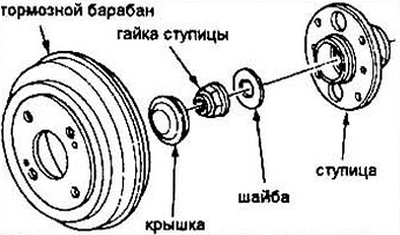
Fig. 5.3 Assembly of the hub and bearing unit
4. Follow the pictures from 5.4a to 5.4p to replace the pads. You should replace all the pads at once, but still work with each wheel in turn.
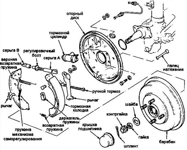
Fig. 5.4a Assembly of a typical drum brake unit
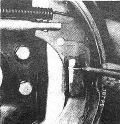
Fig. 5.4b Pull the spring holder with a screwdriver, then turn the tensioner pin until its head matches the slot in the holder - the spring should make a characteristic sound when the tensioner is compressed (repeat with the other spring)
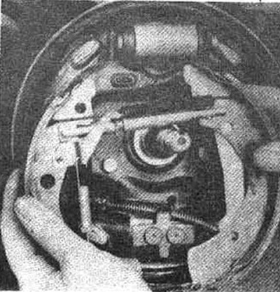
Fig. 5.4c Remove the brake shoe assembly
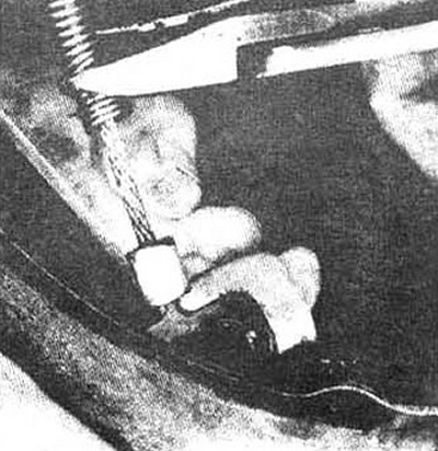
Fig. 5.4g Using a suitable tool, remove the parking brake cable spring, unclip the cable from the parking brake lever
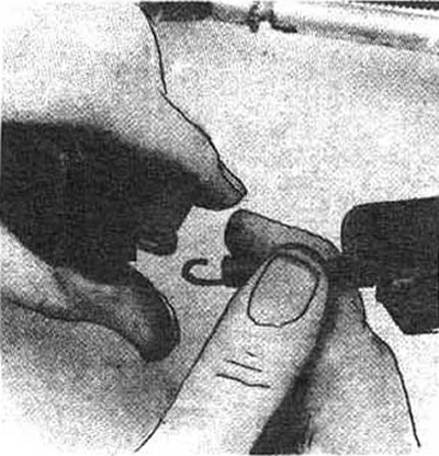
Fig. 5.4d Place the pads on a clean surface. Unfasten the lower return spring from the pads
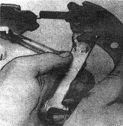
Fig. 5.4g Remove the self-adjusting mechanism lever and its spring from the drive shoe
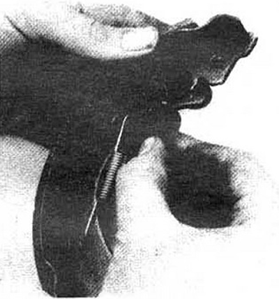
Fig. 5.4e By rocking the parking brake lever, release the adjusting bolt eyelet from its groove on the driven shoe. Disconnect the shoes
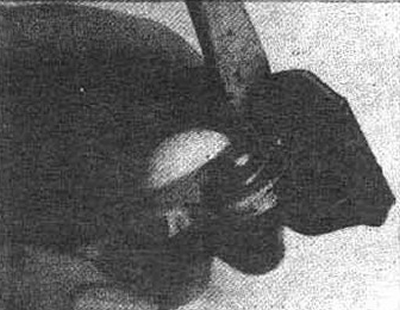
Fig. 5.4z Remove the retaining ring and dismantle the parking brake lever
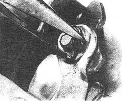
Fig. 5.4i Install the parking brake lever onto the new shoe. Press the ends of the lock washer together
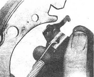
Fig. 5.4k Place the spring of the self-adjusting mechanism on the lever and the driven shoe, insert the lever stick into the hole in the shoe
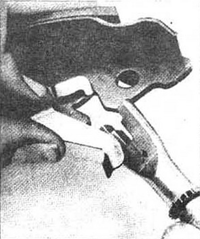
Fig. 5.4l Insert the short earring of the adjusting bolt into the slot of the leading shoe with the grip of the self-adjusting lever
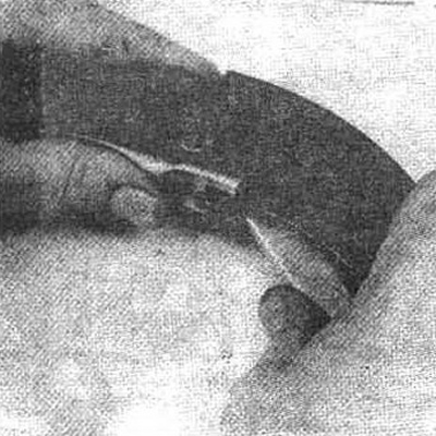
Fig. 5.4m Place the upper return spring on both pads, insert the second earring of the adjusting bolt into the slot of the pad
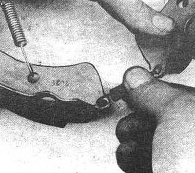
Fig. 5.4n Bring the lower ends of the pads together and install the lower return spring
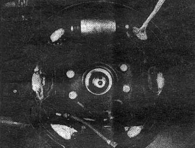
Figure 5.4 o Lubricate the contact points of the pads with the support plate with a high-melting grease
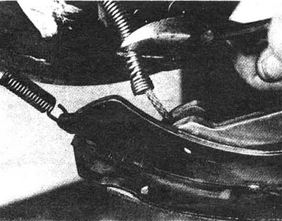
Figure 5.4 p Squeeze the spring of the parking brake cable and connect the cable to the lever
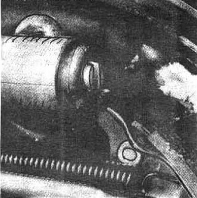
Fig. 5.4p Install the pads on the support disc. Make sure that the slots in the brake cylinder and the pad protrusion match
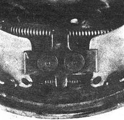
Fig. 5.4c Pass the tensioner pins through the holes in the support disk, install the spring retainer (see fig. 5.4c), make sure that the parking brake cable spring and lower return spring remain behind the locking bracket as shown in the figure
5. Before installing the drum, inspect it for cracks, chips, deep burrs and corrosion spots. If corrosion cavities cannot be removed with sandpaper, as well as other defects, the drum surface must be restored by boring.
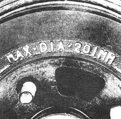
Fig. 5.5 Marking of the maximum internal diameter of the drum
Note: The drum bore should not exceed the maximum permissible brake drum size. This diameter is stamped on the drum rim. If you think that boring is not required, smooth out the largest surface defects with sandpaper.
6. Install the hub and vacuum unit, washer and new nut (if these parts were removed). Tighten the nut to the torque specified in specifications for Chapter 10. Install the brake drum.
7. Mount the wheels, lower the car. Tighten the wheel nuts.
8. Perform several successive braking applications while moving forward and backward to adjust the brakes and brake pedal.
9. Check the operation of the brakes on a closed area.
[Article source on the website: HondaBook.ru]