
Note: Replacement of brake pads must be performed simultaneously on both wheels of one axle. Cleaning of brake parts is performed only with denatured alcohol.
Note: When servicing brakes, use only high quality parts with recognizable markings.
1. Remove the brake fluid reservoir cap.
2. Loosen the wheel nuts, lift the car and place it on stands.
3. Remove the wheel. We do not recommend working with several wheels at the same time. Replace the pads one by one.
4. Carefully inspect the brake disc (see Section 4) - if it requires repair, it must be carried out before replacing the pads.
Front pads
5. Push the piston into the cylinder to provide sufficient clearance for the new pad. You can use a clamp to make this process easier. When the piston enters the brake caliper cylinder, the fluid level in the reservoir rises. Make sure there is no overflow: remove excess brake fluid if necessary.

Fig. 2.5 Releasing the brake cylinder
6. The next steps for replacing the pads are shown in Fig. 2.6a-2.6b. After completing the work on this point, proceed to point 8. Rear pads.
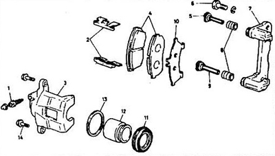
Fig. 2.6a Assembly of the front brake from Tokico: 1 - bleed nipple; 2 - brake shoe retainer; 3 - support; 4 - pads; 5 - guide pin; 6 - guide bolt; 7 - shoe guide; 8 - anther; 9 - guide pin; 10 - shoe pusher; 11 - anther; 12 - piston; 13 - piston seal; 14 - caliper bolt.
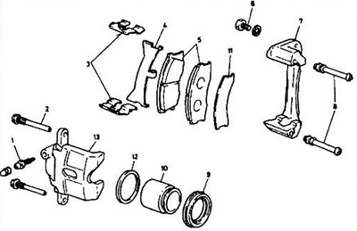
Fig. 2.6b Assembly of the Sumitomo front brake: 1 - bleed nipple; 2 - caliper bolt; 3 - brake shoe retainer; 4 - retainer plate; 5 - pads; 6 - guide bolt; 7 - shoe guide; 8 - guide bushing; 9 - anther; 10 - piston; 11 - shoe pusher; 12 - piston seal; 13 - support.
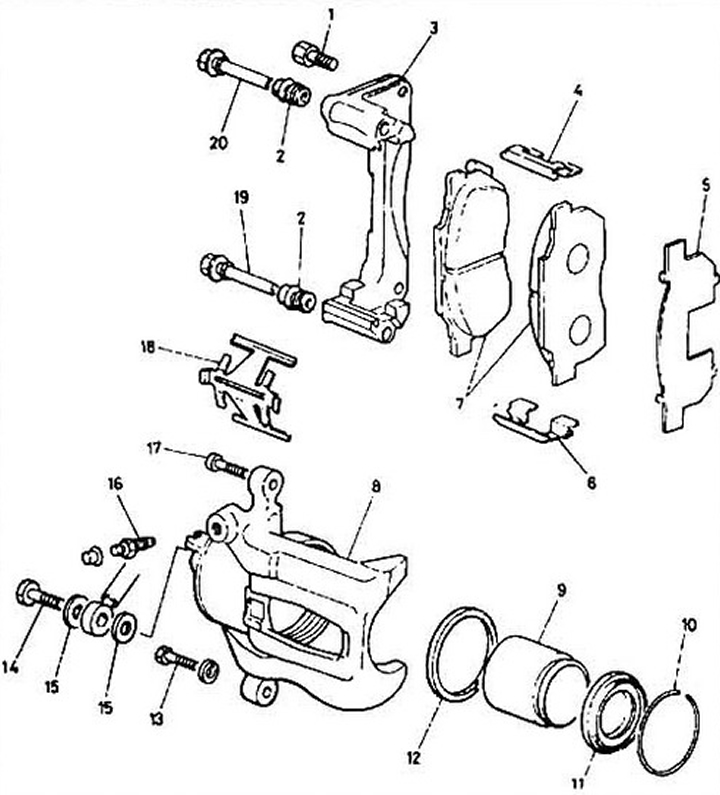
Fig. 2.6c Assembly of the front brake from Nissin: 1 - guide bolt; 2 - anther; 3 - guide; 4 - brake shoe retainer; 5 - pad pusher; 6 - retainer; 7 - block; 8 - support; 9 - piston; 10 - dust cover ring; 11 - anther; 12 - seal; 13 - guide bolt; 14 - banjo bolt; 15 - sealing washers; 16 - bleed nipple; 17 - caliper bolt; 18 - holder; 19, 20 - guide bushings.
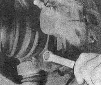
Fig. 2.6g Remove the caliper mounting bolt
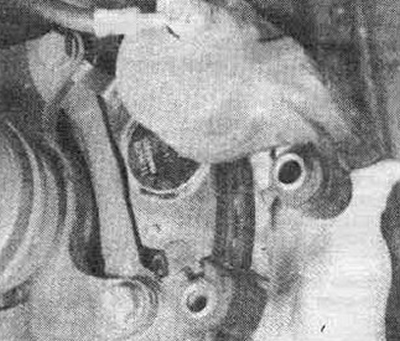
Fig. 2.6d Turn the support upwards
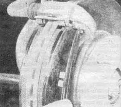
Fig. 2.6e Remove the shoe pusher
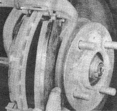
Fig. 2.6g Remove the outer shoe
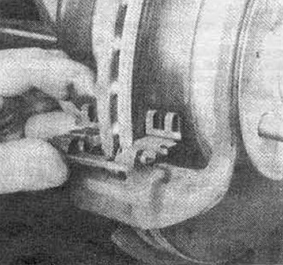
Fig. 2.6i Remove the brake shoe retainers (the lower retainer is shown): pay special attention to the position of the retainer springs
7. Following the instructions in Figures 2.7b-2.7e, replace the rear brake pads.
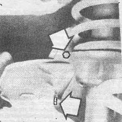
Fig. 2.7a Remove the protection bolts (arrows) and the caliper protection
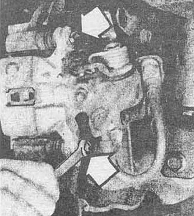
Fig. 2.7b Remove the caliper mounting bolts...
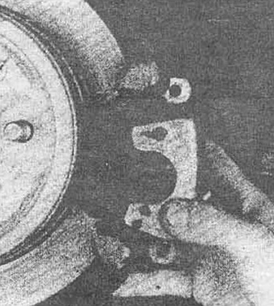
Fig. 2.7c... and remove the caliper from the bracket. Hang the caliper (not for brake hose 1)
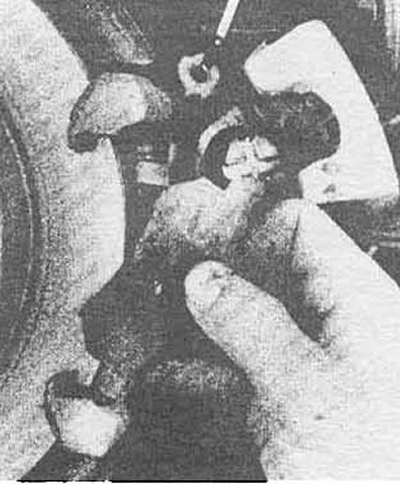
Fig. 2.7g Remove the pusher and outer shoe
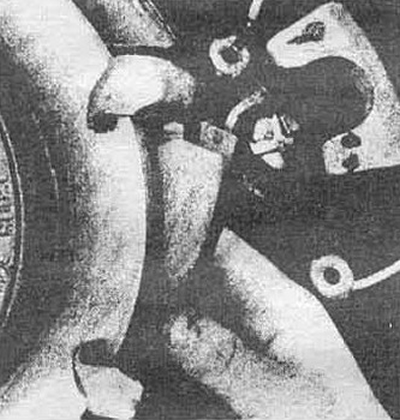
Fig. 2.7d Remove the pusher and the inner shoe
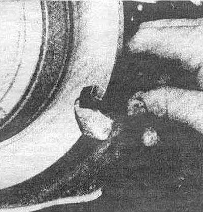
Fig. 2.7e Remove the brake shoe retainers (the bottom is shown)
Front and rear pads
8. Apply anti-noise compound to new pads according to the manufacturer's instructions.
9. Install the pads on the pushers.
10. Install the clamps on the guide. Lubricate them with a thin layer of silicone grease.
11. Install the pads into the guide.
12. If replacing the front pads, install the caliper mounting bolts and tighten them to the torque specified in the specification and proceed to step 15. If replacing the rear pads, proceed to step 13.
Rear pads
13. Using round nose pliers, turn the piston clockwise and push it in. Then rotate the piston until its grooves align with the tabs of the inner pad installed in the caliper.
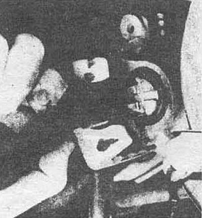
Fig. 2.13 Adjusting the piston position when replacing the pads
If the piston boot becomes warped during adjustment, turn the piston in the opposite direction until the boot is restored to its original shape.
14. Install the caliper guard.
Front and rear pads
15. Install the wheel and lug nuts, lower the vehicle and tighten the nuts.
16. Check the brake fluid level. Top up if necessary (see Chapter 1).
17. Press the brake pedal several times to install the pads in their place. Check the operation of the brakes on a closed area.
(You will find the original on the portal: «HondaBook.ru»)