
Warning! The replacement of shoes must be carried out simultaneously on both brake mechanisms. See also the warning at the beginning Removal, repair and installation of disc brake calipers!
Note: At the same time as replacing the brake shoes, their tension and guide springs should also be replaced, as they stretch/sag over time as a result of constant cyclic mechanical and thermal loads, ceasing to develop the required force, which leads to the brakes seizing and accelerated wear of the drums.
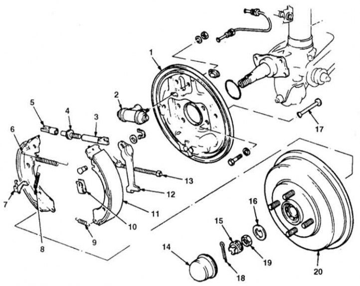
Rear wheel drum brake components
1 - Brake mechanism shield; 2 - Wheel cylinder; 3 - Fork of the expansion bar; 4 - Adjusting bolt; 5 - Fork of the expansion bar; 6 - Upper tension spring; 7 - Automatic regulator lever; 8 - Automatic regulator spring; 9 - Lower tension spring; 10 - Guide spring; 11 - Brake shoe; 12 - Parking brake actuator; 13 - Parking brake cable; 14 - Wheel bearing cap; 15 - Pin lock; 16 - Rear axle spindle washer; 17 - Anchor pin; 18 - Cotter pin; 19 - Spindle nut; 20 - Brake drum
1. Loosen the rear wheel nuts. Jack up the rear of the car and place it on stands. Support the front wheels with wheel chocks. Remove the rear wheels and release the parking brake.
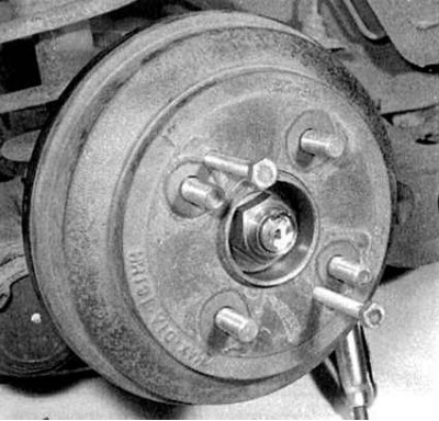
2a. The design of the drum brake mechanism is shown in the illustration above. Remove the brake drum from the hub. The drum should be removed fairly freely, but if difficulties arise, carefully tap it with a soft-faced hammer or screw a pair of M8 bolts into the threaded holes (see accompanying illustration).
3. It is easier to replace the shoes after removing the hub assembly from the axle journal (remove the wheel bearing cover, loosen the spindle nut and remove the washer (see Chapter Suspension and steering).
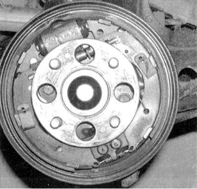
4a. Proceed as follows to check the condition of the components and replace the brake shoes. Proceed strictly in the specified order. Remember that all four shoes of both brake mechanisms must be replaced at the same time.
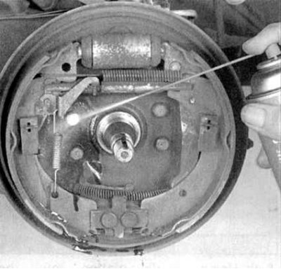
4b. Before dismantling the components, wash them with a special cleaner, then dry them (DO NOT BLOW OFF BRAKE DUST WITH COMPRESSED AIR UNDER ANY CIRCUMSTANCES!).
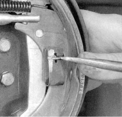
4c. Use a screwdriver to push the guide spring down, then turn the anchor pin with the lock parallel to the groove in the spring – the latter should bounce off the shoe.
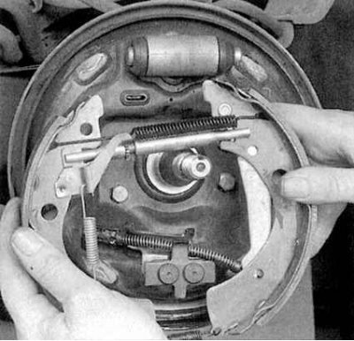
4d. Remove the shoe assembly from the brake shield (the hub has been removed for clarity).
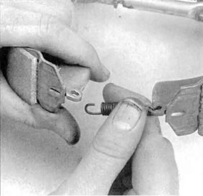
4e. Disconnect the tension spring.
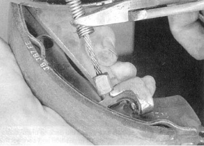
4f. Pull the spring on the parking brake cable back enough to be able to grab the cable with side cutters, keeping the spring compressed (try not to cut the torso); now disconnect the cable end from the parking brake actuator lever.
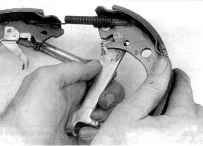
4g. Rotate the parking brake actuator lever away from the rear brake shoe - this should release the fork of the adjusting bolt of the expansion bar from its mounting groove in the shoe, which will allow the shoes to be separated.
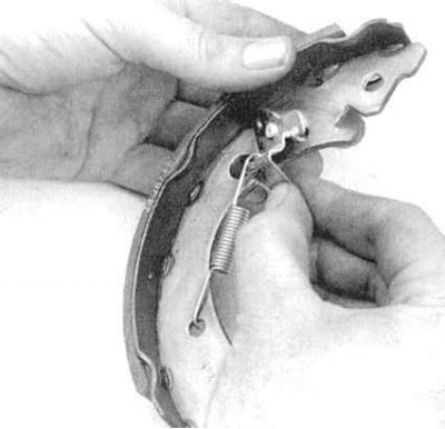
4h. Remove the automatic adjuster lever and spring from the front brake shoe.
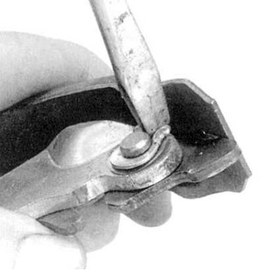
4i. Remove the retainer and disconnect the parking brake actuator lever from the rear shoe (do not lose the bent washer installed under the retaining ring).
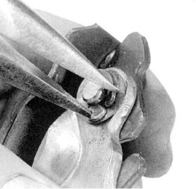
4j. Attach the new rear shoe to the lever (don't forget to put a bent washer under the retainer); use needle-nose pliers to squeeze the ends of the clip together.
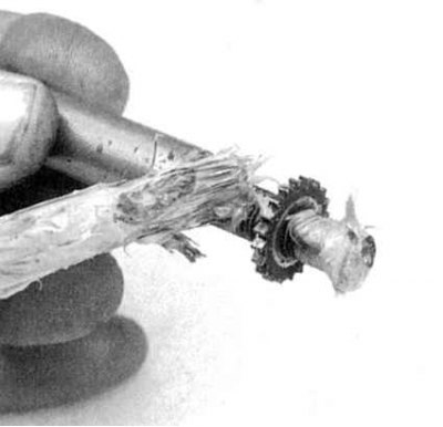
4k. Clean the adjusting bolt and the forks of the expansion bar, then lubricate them with high-melting grease.
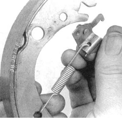
4l. Hook the automatic adjuster spring into the hole in the new front shoe, then insert the lever pin into the other special hole in the shoe.
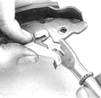
4m. Insert the short fork of the expansion bar into its groove in the front shoe (make sure that the fork is correctly engaged with the automatic regulator lever).
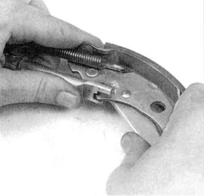
4n. Attach the upper tension spring to both brake shoes, spread the lower ends of the shoes and insert the fork of the expansion bar into the groove in the rear shoe (make sure the fork step is positioned correctly).
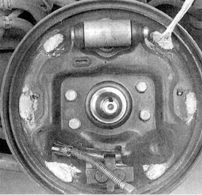
4o. Lubricate the surfaces of the brake shield that contact the shoes with high-melting grease.
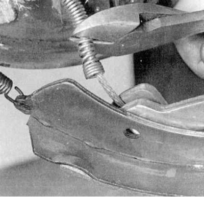
4p. Use side cutters to compress the spring of the parking brake drive cable (do not cut the cable) and, holding it in this position, connect the cable end to the actuator lever.
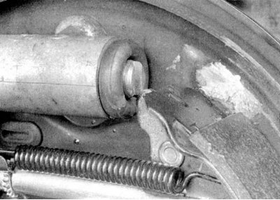
4q. Install the shoe assembly onto the brake shield, seating the upper ends of the shoes into the grooves in the wheel cylinder pistons; connect the lower tension spring to the shoes.
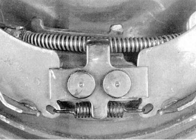
4r. Insert anchor pins into holes in brake shield and shoes, install guide springs; turn the fingers, fixing the springs; make sure that the parking brake cable spring and the lower tension spring are positioned under the anchor bracket bars as shown in the picture.
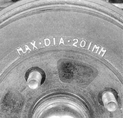
5. Before installing the drum, check it for burrs, grooves, traces of overheating and other defects. If serious damage is detected, traces of which cannot be eliminated by processing the drum with fine-grained sandpaper, the drum should be given for turning (in compliance with the maximum permissible repair diameter). If the drum cannot be turned without violating the maximum permissible internal diameter (stamped on the drum - see accompanying illustration), it will have to be replaced. If it is not possible to turn the drums, at least carefully clean their working surfaces with fine-grained sandpaper.
Note: The authors of this Manual recommend turning the drums regardless of their condition in order to remove any defects and eliminate ovality.
6. Reinstall the hub and wheel bearing assembly, install the washer and screw on the new spindle nut, tightening it to the required torque (see Specifications to the Chapter Suspension and steering).
7. Replace the wheel, then lower the vehicle to the ground and tighten the wheel nuts to the specified torque (see Specifications to the Chapter Routine maintenance).
8. Brake the vehicle several times while moving both forward and reverse in order to automatically adjust the brake mechanisms.
9. Before operating the vehicle, make sure that the brakes are functioning properly.