
General information
When the vehicle is equipped with a conventional brake system, depressing the foot brake pedal suddenly causes the wheels to lock. In this case, the grip of the tread with the road surface is disturbed, and the car can go skidding, losing controllability. Anti-lock brake system (ABS) It is designed to prevent premature blocking of the wheels by continuously controlling the speed of their rotation during braking by modulating the pressure of the hydraulic fluid in each of the brake mechanisms.
ABS consists of two main subsystems: electrical and hydraulic. The electrical part of the system includes four wheel speed sensors, a control processor and a set of connecting wiring. The hydraulic part includes a pressure modulator, disc brake calipers and hydraulic lines connecting the components.
The principle of operation of the system is quite simple. Each of the wheels is equipped with an individual speed sensor. The sensor consists of a rotor (rings with teeth evenly spaced around its perimeter) and a sensitive element in the form of a magnetized coil. The sensitive element of the sensor captures the moments of the passage of the teeth of the rotor and converts the information received into electrical signals that are continuously transmitted to the ABS control processor. Based on the results of processing the incoming signals, the processor receives information about the relative speed of rotation of each of the wheels. As long as all four wheels rotate at the same speed, ABS is in a passive state. As soon as any of the wheels starts to block, the processor detects a change in the input signal and generates a command to operate the modulator, which instantly relieves the pressure of the hydraulic fluid in the brake mechanism of the corresponding wheel. As soon as normal rotation of the wheel is restored, the processor suspends the functioning of the modulator.
In reality, the ABS operation is much more complicated than it might seem, so the compilers of this manual do not recommend car owners to attempt to repair the system on their own. In the event of a problem, it would be wiser to contact a car service specialist.
Reading ABS Fault Codes
1. When starting the engine, the ABS warning lamp on the vehicle's instrument panel should turn on briefly and go out again almost immediately. If, due to any violation, the lamp remains on after the engine is started, the ABS processor writes the corresponding digital code to the memory of the self-diagnosis unit. To read the code on the control lamp:
- a) Release the diagnostic connector plug from its cover located under the glove box (see chapter Engine management systems);
- b) Connect the two pins of the connector with a jumper wire.
Civic Models (and Integra since 1998 vol.)
1. Turn on the ignition (do not start the engine). Two seconds after turning the key to the ON position, the ABS processor will begin to output the trouble codes stored in its memory, calling for the blinking of the ABS warning lamp on the car's dashboard. The flashing of the codes starts with a pause of 3.6 seconds. Then a sequence of pulses of the first code stored in the memory of the processor is issued (a series of flashes of the main code, then, after a pause of a second, a series of flashes of the additional code [if any]). Further, after a five-second pause, a combination of codes is displayed (main and additional) second fault, etc. The system allows you to read any number of codes. After writing down the read information, compare it with the code map shown on the accompanying table.
| Fault code | Possible source of malfunction |
| 11 | Right front wheel speed sensor (open/short circuit in the circuit) |
| 12 | Right front wheel speed sensor (electrical interference or disturbance of the stability of the generated signals) |
| 13 | Left front wheel speed sensor (open/short circuit in the circuit) |
| 14 | Left front wheel speed sensor (electrical interference or disturbance of the stability of the generated signals) |
| 15 | Right rear wheel speed sensor (open/short circuit in the circuit) |
| 16 | Right rear wheel speed sensor (electrical interference or disturbance of the stability of the generated signals) |
| 17 | Left rear wheel speed sensor (open/short circuit in the circuit) |
| 18 | Left rear wheel speed sensor (electrical interference or disturbance of the stability of the generated signals) |
| 21 | Right front wheel speed sensor rotor |
| 22 | Left front wheel speed sensor rotor |
| 23 | Right rear wheel speed sensor rotor |
| 24 | Left rear wheel speed sensor rotor |
| 31 | Right front wheel sensor input solenoid coil |
| 32 | Right front wheel sensor output solenoid coil |
| 33 | Left front wheel sensor input solenoid coil |
| 34 | Left front wheel sensor output solenoid coil |
| 35 | Right rear wheel sensor input solenoid coil |
| 36 | Right rear wheel sensor output solenoid coil |
| 37 | Left rear wheel sensor input solenoid coil |
| 38 | Left Rear Wheel Sensor Solenoid Output |
| 41 | Right front wheel lock |
| 42 | Left front wheel lock |
| 43 | Right rear wheel lock |
| 44 | Left rear wheel lock |
| 51 | Motor lock |
| 52 | Motor does not turn on |
| 53 | Motor won't turn off |
| 54 | Faulty safety relay |
| 61 | Excessively low voltage in the ignition circuit |
| 62 | Excessively high voltage in the ignition circuit |
| 71 | Wheels of various diameters installed |
| 81 | Faulty CPU and ROM/RAM unit (ROM/RAM) |
Integra models through 1997 vol.
1. Turn on the ignition (do not start the engine). Two seconds after turning the key to the ON position, the ABS processor will begin to output the trouble codes stored in its memory, calling for the blinking of the ABS warning lamp on the car's dashboard. The flashing of the codes starts with a pause of 2 seconds. Then a sequence of pulses of the first code stored in the memory of the processor is issued (a series of flashes of the main code, then, after a pause of a second, a series of flashes of the additional code [if any]). Further, after a five-second pause, a combination of codes is displayed (main and additional) second fault, etc. The system allows you to read up to three codes.
2. If you lost count while reading the codes, turn off the ignition, then turn it back on and start again. Do not forget that any ABS repair should be carried out by car service specialists.
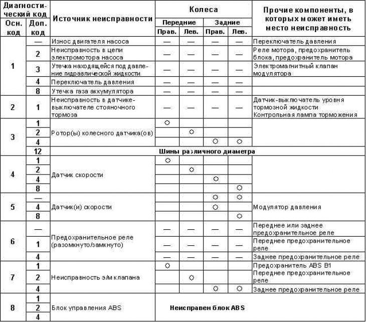
ABS Fault Code Map for 1997 Integra models.
Clearing ABS memory
After fixing the identified problems in the system, the processor memory should be cleared.
Civic Models (and Integra since 1998 vol.)
1. To clear the processor memory, remove the jumper wire from the diagnostic connector terminals, then remove the 15 A ABS B2 fuse from the mounting block installed in the engine compartment of the car for at least three seconds. Replace the fuse and connect the plug of the diagnostic connector to the cover.
Integra models through 1997 vol.
1. Without removing the jumper wire, turn off the ignition, then depress the foot brake pedal and turn the ignition key back to the ON position. When the ABS warning lamp on the instrument panel goes out, release the pedal - the lamp should turn on again. Depress the pedal again and wait for the lamp to turn off. Release the pedal.
2. The control lamp should blink twice, confirming the clearing of the processor memory, after which you can turn off the ignition, remove the jumper wire and restore the original connection of the diagnostic connector.