
Functional check
1. Without starting the engine, depress the foot brake pedal several times. Check for any change in pedal travel.
2. Keeping the pedal depressed, start the engine. If immediately after starting the pedal slightly "fails", therefore, the vacuum brake booster is working properly.
Leak test
1. Run the engine for a couple of minutes, then shut it off. Slowly depress the foot brake pedal several times. If the pedal travel is gradually reduced with each squeeze, the tightness of the vacuum booster assembly is not broken.
2. Depress the foot brake pedal while the engine is running. Keeping the pedal depressed, stop the engine. If after 30 seconds of keeping the pedal depressed, its position does not change, therefore, the tightness of the vacuum booster assembly is not broken.
Withdrawal
1. The vacuum brake booster unit cannot be repaired and must be replaced as an assembly in case of failure.
2. Remove the GTZ assembly from the vacuum booster (see Removal and installation of the main brake cylinder).
3. Disconnect the hose coming from the engine. Be careful not to damage the hose when removing it from the fitting on the booster assembly.
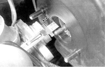
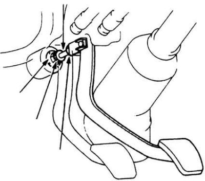
3. Under the instrument panel, find the connection point for the vacuum booster pusher rod to the foot brake pedal.
4. Remove the cotter pin and disconnect the pusher from the pedal.
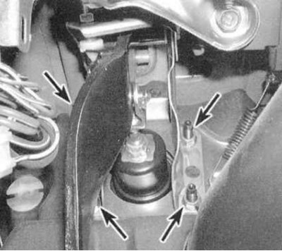
5. From the passenger compartment, give four nuts securing the vacuum booster assembly to the bulkhead of the engine compartment (see accompanying illustration), remove washers (use a flashlight if necessary).
6. Go to the engine compartment and remove the vacuum booster assembly from the studs on the rear bulkhead. Also remove brackets and gaskets.
Installation
1. Installation is carried out in the reverse order to dismantling. Make sure that all fasteners are tightened to the required torque, and that the pins and cotter pins are replaced.
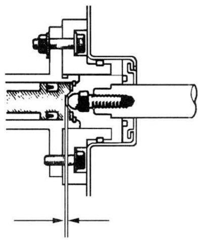
2. When installing a new brake booster, it is necessary to adjust the working clearance of its pusher rod (see accompanying illustration), For what:
- a) Using a manual vacuum pump, create a vacuum on the amplifier to a depth of 508 mm Hg. Art., then measure the protrusion of the pusher above the assembly surface mating with the GTZ (including gasket, if any). Record the measurement result, call it "Size A".
- b) Measure the distance from the GTZ support flange to the end surface of the cylinder (see accompanying illustration). Record the measurement result, hereinafter referred to as "Size B".
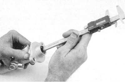
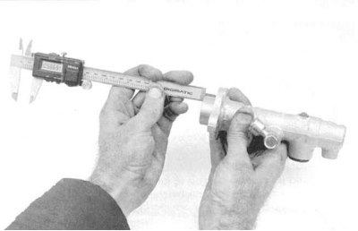
- c) Measure the distance from the end surface of the GTZ to the bottom of the landing pocket at the end of its piston (see accompanying illustration). Record the result by calling it "Size C".
- d) Subtract dimension B from dimension C, then subtract dimension A from the resulting difference. The result obtained will determine the value of the required working clearance.
- e) Compare the calculation result with the requirements Specifications. Make appropriate adjustments if necessary (see below).
3. To adjust the operating clearance of the pusher rod, loosen the toothed locknut and turn the adjuster in the appropriate direction. After completing the adjustment, tighten the locknut and re-measure the clearance. Repeat if necessary.
4. After installing the GTZ, bleed the brake system (see Bleeding the brake system).