
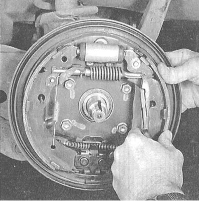
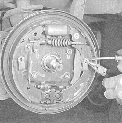
Assembly of the drum brake mechanism of the right rear wheel
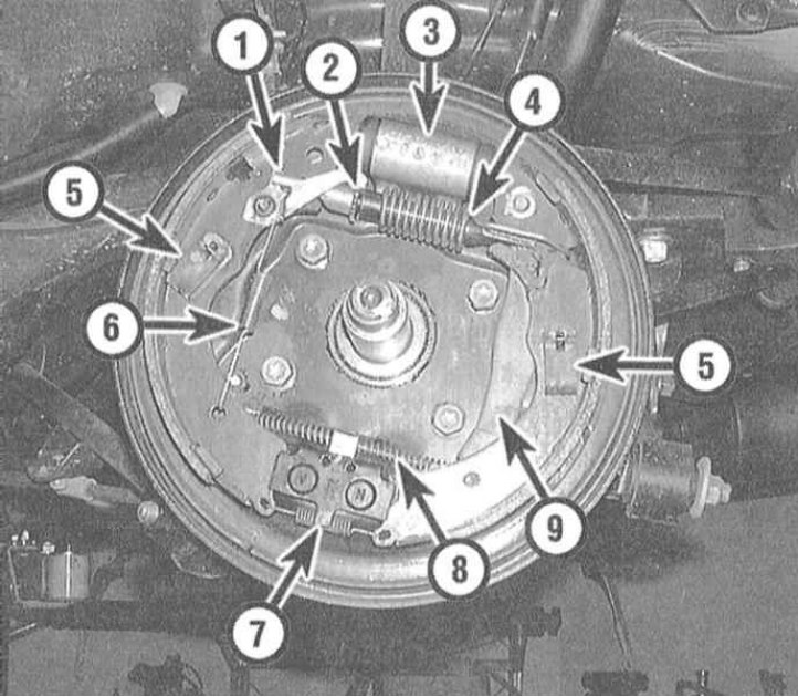
1 - Automatic regulator lever; 2 - Assembling the regulator; 3 - Wheel cylinder; 4 - Upper tension spring; 5 - Guide spring; 6 - Automatic regulator spring; 7 - Lower tension spring; 8 - Parking brake cable; 9 - Parking brake actuator lever
Caution! The replacement of shoes must be carried out simultaneously on both brake mechanisms. See also the warning at the beginning of the Section Removal and installation of disc brake calipers!
At the same time as replacing the brake shoes, their tension and guide springs must also be replaced, as they stretch/sag over time as a result of constant cyclic mechanical and thermal loads, ceasing to develop the required force, which leads to the brakes seizing and accelerated wear of the drums.
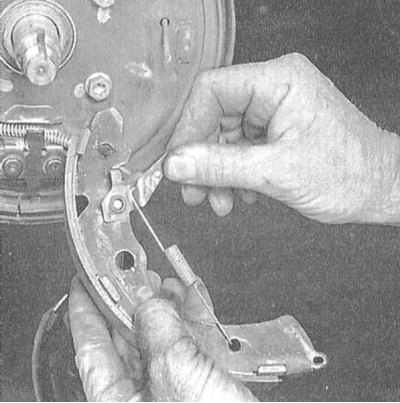
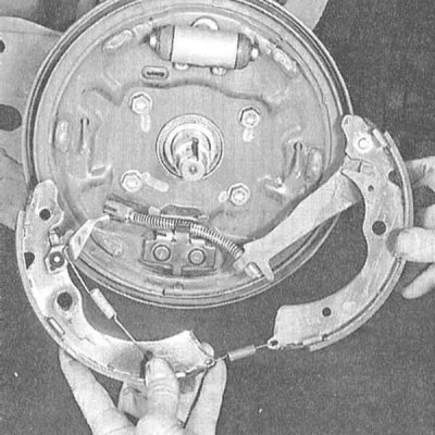
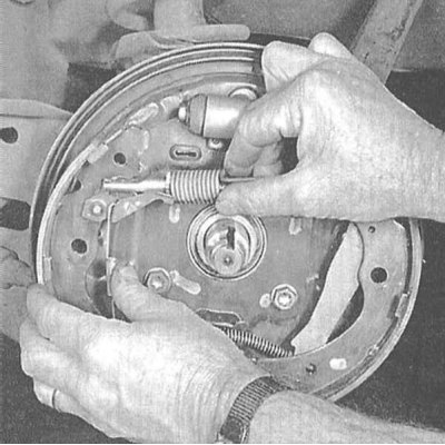
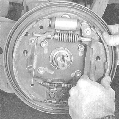
1. Loosen the rear wheel nuts. Jack up the rear of the car and place it on stands. Support the front wheels with wheel chocks. Remove the rear wheels and release the parking brake.
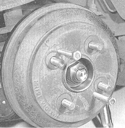
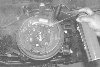
2. Remove the brake drum from the hub. The drum should be fairly easy to remove, but if you have any difficulties, gently tap it with a soft-faced hammer or screw a couple of M8 bolts into the threaded holes. If the drum still cannot be removed, press the brake shoes away from its working surface. Remove the rubber plug from the brake shield, insert a screwdriver into the opening and use it to move the self-adjusting lever away from the adjusting sprocket. Use the second screwdriver to rotate the sprocket until the drum is completely free.
3. It is easier to replace the shoes after removing the hub assembly from the axle journal (remove the wheel bearing cover, loosen the spindle nut and remove the washer (see Chapter Suspension and steering).
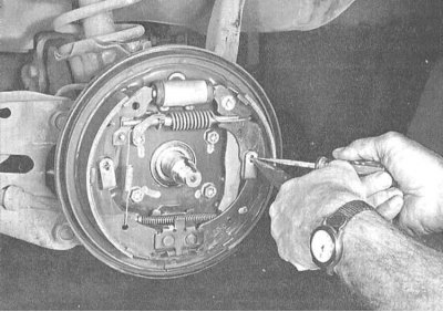
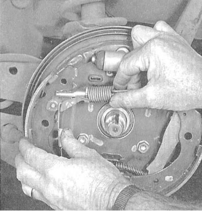
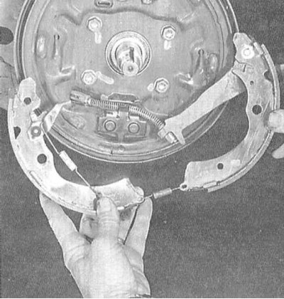
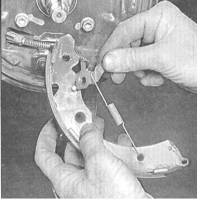
4. Following the instructions in the illustrations, check the condition of the components and replace the brake shoes. Follow the instructions strictly in the specified order. Remember that all four shoes of both brake mechanisms must be replaced at the same time.
 |
 |
 |
 |
 |
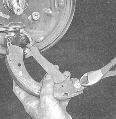 |
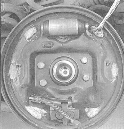 |
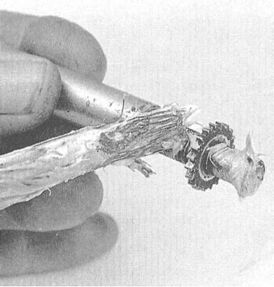 |
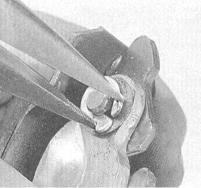 |
 |
 |
 |
 |
 |
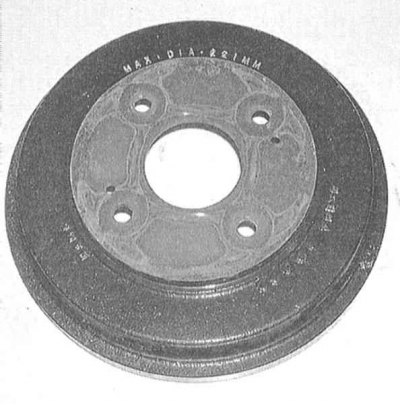
5. Before installing the drum, check it for burrs, grooves, traces of overheating and other defects. If serious damage is detected, traces of which cannot be eliminated by treating the drum with fine-grained sandpaper, the drum should be given for turning (in compliance with the maximum permissible repair diameter).
Note. The authors of this Manual recommend turning the drums regardless of their condition in order to remove any defects and eliminate ovality. If the drum cannot be turned without violating the requirements for the maximum permissible internal diameter (stamped on the drum), it will have to be replaced. If it is not possible to turn the drums, at least carefully clean their working surfaces with fine-grained sandpaper.
6. Reinstall the hub and wheel bearing assembly, install the washer and install the new spindle nut, tightening it to the required torque (see Specifications in Chapter Suspension and steering).
7. Reinstall the drum. Insert a screwdriver into the hole in the brake shield and, by turning the adjuster sprocket, press the shoes against the working surfaces of the drum, then return the sprocket back a little so that the drum begins to rotate freely (preliminary adjustment).
8. Reinstall the wheel, then lower the vehicle to the ground and tighten the wheel nuts to the specified torque (see Specifications in Chapter Settings and ongoing maintenance).
9. Brake the vehicle several times while moving both forward and reverse in order to automatically adjust the brake mechanisms.
10. Before operating the vehicle, make sure that the brakes are functioning properly.
(Information obtained from this source: «hondabook»)