
Note. The procedure is equally applicable to both front and rear disc brakes.
Status check
1. Loosen the wheel nuts, jack up the vehicle and place it on jack stands. Remove the appropriate wheel, then screw a couple of nuts back onto the mounting studs, placing 3 mm washers under them to secure the brake disc (if the two disc fixing screws are not yet removed, there is no need to tighten the nuts). When checking the rear brake disc, be sure to release the parking brake.
2. Remove the brake caliper (see Removal, repair and installation of disc brake calipers) and tie it aside with a wire to the suspension element without disconnecting the brake hose.
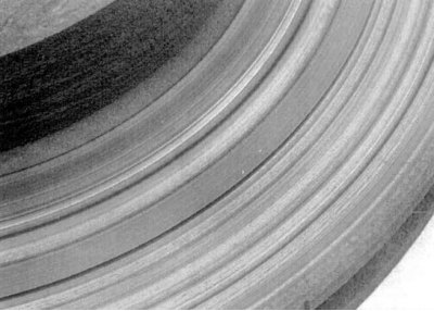
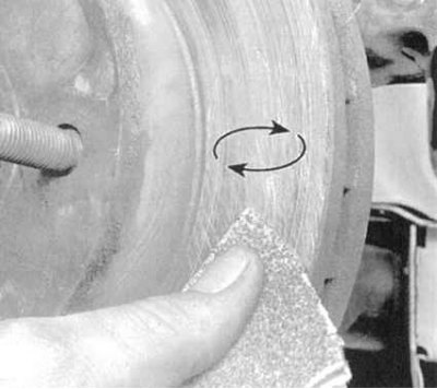
3. Perform a visual check of the condition of the working surface of the disc (see accompanying illustration). Light defects can be removed with fine-grained sandpaper. To remove grooves deeper than 0.38 mm, the disc should be machined.
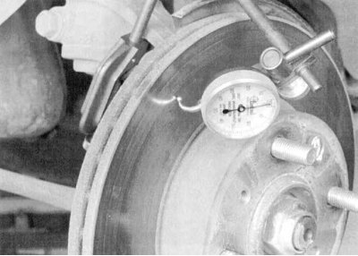
4a. If pedal pulsations are noticed during braking, the magnitude of the lateral runout of the brake disc should be assessed. Attach plunger type dial gauge (DTI) at a distance of about 12.7 mm from the outer edge of the disc (see accompanying illustration).
4b. Zero the instrument and start spinning the disc. The result of the measurement should not go beyond the limits specified in Specifications allowable range, otherwise the disk must be given to the groove.
Note. The compilers of this Guide recommend turning the discs, regardless of their condition, in order to remove all kinds of defects from the working surfaces. In extreme cases, you can limit yourself to processing the disk with fine-grained sandpaper.
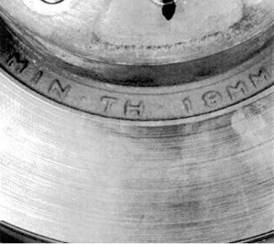
5a. When grooving a disc, special attention should be paid to compliance with the requirements Specifications to its minimum allowable thickness. Appropriate marking is provided on the end surface of the disc (see accompanying illustration).
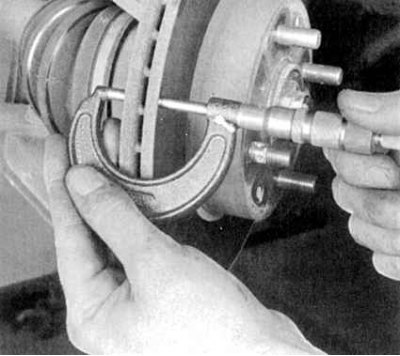
5b. The disc thickness is measured with a micrometer (see accompanying illustration).
Withdrawal
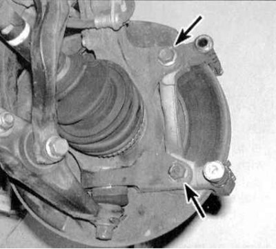
1a. Turn out two bolts of fastening of an anchor bracket of a support to a rotary fist (see accompanying illustration).
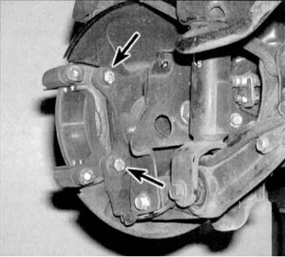
1b. Or (on the rear wheel brake) bolts of fastening of a bracket to a trailing arm of a suspension bracket. Remove the bracket.
2a. Remove the two wheel nuts used to secure the disc to the hub/remove the two fixing screws (see accompanying illustration).
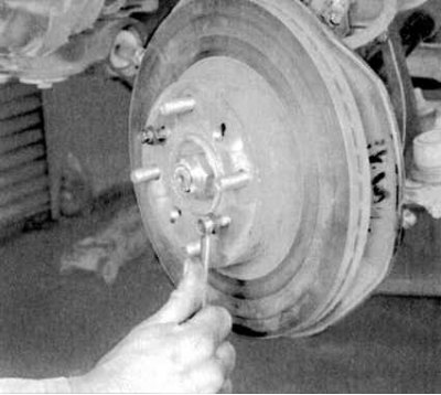
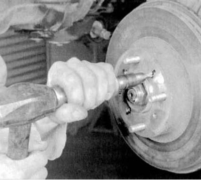
2b. Remove the disc from the wheel hub. If the disk "stuck" to the hub, it can be squeezed out by screwing a pair of bolts of a suitable size into the mounting holes (see accompanying illustration).
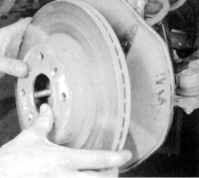
2c. Tighten the bolts evenly and progressively until the disc is completely loose. When removing the disc, take care not to damage the threads of the wheel studs (see accompanying illustration).
Installation
1. Gently slide the disc onto the hub (again try not to damage the wheel studs). Screw in the fixing screws.
2. Install the caliper anchor bracket on the disc. Tighten the bracket and caliper mounting bolts to the required torque.
3. Replace the wheel, lower the vehicle to the ground and tighten the wheel nuts to the required torque (see Specifications to the head Current service). Depress the brake pedal/cock the parking brake lever several times to seat the pads on the disc. If the brake hoses have not been disconnected, there is no need to bleed the hydraulic system. Before starting the operation of the vehicle, make sure that the brakes are working properly.