
2. While holding the box flange, remove the nut. Remove the lock washer and remove the flange. Use a puller if necessary.
3. Remove the bolts of the driven gear, pull it out of the box body.
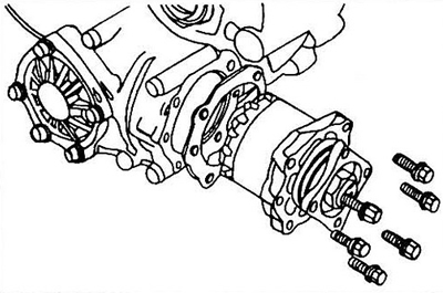
Pic. 9.3 Attachment of the driven gear to the transfer case
4. Use a screwdriver to carefully remove the oil seal. Do not damage the gear shaft and seating surfaces.
5. Using a head or a suitable piece of pipe, install a new gland.
6. Lubricate the inner and outer sealing lips.
7. Insert flange, lock washer and nut.
8. Install the driven gear assembly into the box body.
9. Torque the flange nut to specification.
10. Remove the driven gear assembly from the box again.
11. Measure the driven gear bearing preload.
This measurement, which indicates the resistance to rotation of the driven gear bearing, is very important. Place a 22 mm socket on the flange nut and insert a torque wrench into it, rotate the flange with the wrench. Compare key force with data
Specifications If the pre-pull force is less than specified, slightly tighten the flange nut. If the force is greater than the specified a new spacer is required between the bearing inside the housing. We recommend replacing the spacer only at a service station.
12. Install the driven gear assembly in place and tighten the mounting bolts to specification.
13. Attach the cardan shaft to the transfer case flange (see Section 4) and tighten the bolts to the torque given in specifications.