
Note: Use new rings for assembly.
2. When removing the rings, try not to damage the piston surfaces.
3. Remove any carbon deposits from the piston head. You can use a brush or fine sandpaper for this. Never use a mechanically driven wire brush: the piston material is very soft and easily damaged.
4. Clean the piston grooves from carbon deposits using a special tool or ring fragments. Remove only carbon deposits without damaging the groove surfaces.
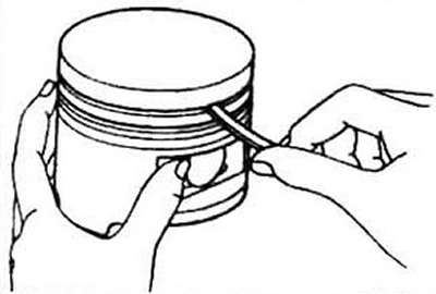
Fig. 17.4 The piston grooves can be cleaned with a piece of an old ring
5. Wash the piston/connecting rod assembly and dry it. Make sure that the drain holes in the oil ring groove are free of deposits.
6. If the block has not been bored, pistons are not necessary, but rings should be replaced in any case.
7. Inspect the piston for cracks around the skirt, pin bosses and inter-ring bridges.
8. There should be no scratches or scoring on the skirt, holes in the head, or burnout on the piston edges. If there are signs of scoring on the skirt, the engine overheated during operation or had abnormal combustion. In this case, carefully inspect the cooling and lubrication systems. Holes in the piston head indicate abnormal combustion ("pre-ignition").
Burnout of the piston head edges indicates detonation combustion. This should be kept in mind when starting the repaired engine and correcting the carburetor adjustments, ignition, operation of the exhaust gas recirculation system, air suction past the carburetor.
9. Small spots of corrosion on the piston indicate coolant leakage into the combustion chamber and/or crankcase. Eliminate leaks during assembly.
10. Measure the side clearance between the new piston ring and the groove. Take measurements in three or four places around the circumference. If the clearance is greater than the permissible value, replace the pistons.
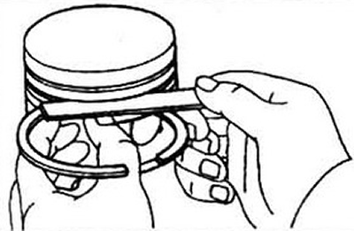
Fig. 17.10 Measure the lateral clearance between the ring and the groove at several points around the circumference
11. Measure the piston diameter and calculate the clearance in the piston-cylinder pair (see section 15). Measure the piston along the skirt in two planes, parallel and perpendicular to the pin axis and 16 mm from the bottom of the skirt. If the gap is greater than the permissible value, the block requires boring to the next repair size, with the corresponding replacement of the piston and rings.
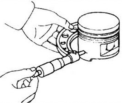
Fig. 17.11 The piston diameter is measured in a plane perpendicular to the piston ring axis and at a distance of 16 mm from the skirt cut
12. Check the clearance in the piston/pin/connecting rod joint by twisting the piston and connecting rod in opposite directions. Excessive mutual movement indicates the need to replace the unit.
13. It is not recommended to carry out work on disassembling the piston/connecting rod unit and restoring its functionality independently.
14. Check the connecting rod for cracks and other damage. Remove the connecting rod cap and remove the bearings. Make sure there are no scratches, abrasions or dents on the bearing seats. Assemble the connecting rod, tightening the nuts by hand.
Note: If the engine was stopped by a knock from a pin or connecting rod bearing, replace the connecting rod.