
Preparation
1. Before installing the connecting rod and piston assemblies, the cylinder walls must be carefully wiped, traces of step wear must be completely removed from their upper edges, and the chamfer must be removed. It is assumed that the crankshaft has already been installed in its regular place in the block.
2. Remove the cover of the lower connecting rod head of the first cylinder piston (make sure there are factory marks or marks applied during dismantling). Remove the old bearing shells from the connecting rod head and its cover and carefully wipe their beds with a clean, lint-free cloth.
Checking the working clearance of the connecting rod bearing
Note: Try not to touch the surfaces of new bearings with bare hands to avoid unwanted contact of bearings with traces of oil and chemically aggressive substances that are always present on fingers.
1. Wipe the back of the new upper bearing shell and place it in the bearing bed in the connecting rod head. Make sure that the guide tongue of the bearing shell fits into the corresponding groove in the connecting rod. Do not tap the bearing shell into the bed with a hammer under any circumstances. Do not lubricate the bearing with anything at this stage.
2. Wipe the back of the second bearing shell and place it in the connecting rod lower head cover. Again, make sure that the tongue fits into the corresponding groove. Do not use any lubricant - it is extremely important that the mating surfaces of the bearing and connecting rod remain absolutely clean and dry.
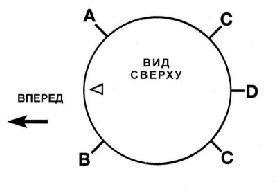
3. Position the piston rings with the locks as shown in the illustration.
Attention! DO NOT position the ring locks coaxially with the piston pin or perpendicular to its axis!
4. Lubricate the piston and piston rings with clean engine oil.
5. Place the ring crimping tool mandrel on the piston. Leave the piston skirt protruding from the tool mandrel by approximately 6.4 mm to allow free insertion into the cylinder. The rings should be crimped flush with the piston forming surface.
6. Turn the crankshaft so that the journal of the first crank is in the BDC position. Lubricate the mirror of the first cylinder with engine oil.
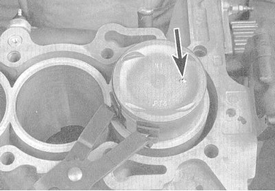
7. With the assembly facing forward along the engine with the mark in the form of a recess or arrow on the piston bottom, carefully insert the connecting rod into the first cylinder of the block. Insert the piston skirt into the cylinder, firmly pressing the lower edge of the ring crimping tool mandrel to the surface of the block.
8. Tap the top edge of the mandrel to ensure that it is pressed tightly against the block along the entire perimeter of the bottom edge.
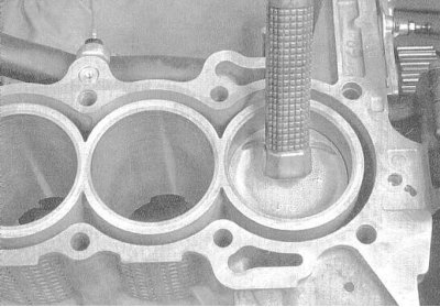
9. Carefully tap the piston bottom with a wooden hammer handle and insert the piston into the cylinder, simultaneously directing the lower head of the connecting rod onto the journal of the corresponding crankshaft crank. The piston rings may suddenly jump out from under the tool holder, so constantly monitor the tightness of the pressure on its block. Do not rush, and if the slightest resistance occurs, immediately stop tapping the piston. Find out the cause of the jam and eliminate it. Do not attempt to push the piston into the cylinder by force under any circumstances - this may lead to mechanical damage to it or destruction of the piston rings.
10. After inserting the connecting rod and piston assembly into the engine, before final installation of the connecting rod lower head cover, the operating clearance of the crankshaft connecting rod bearing should be checked.
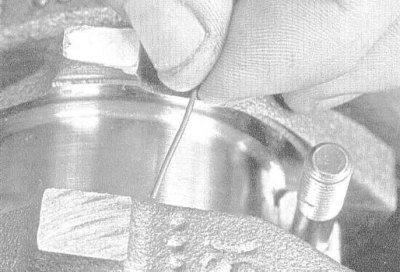
11. Cut a piece of calibrated plastic wire from the Plastigage measuring kit, slightly shorter in length than the width of the connecting rod bearing shell, and lay it along the first connecting rod journal of the crankshaft, parallel to the axis of the latter.
12. Wipe the bearing surface in the connecting rod cap and install the cap on the connecting rod. Make sure that the mark on the cap is facing the same direction as the mark on the connecting rod.
13. Replace the cover mounting bolts and tighten them to the required torque in three stages.
Note: To prevent the wrench from jamming, use a thin-walled socket head. If there is any sign of the wrench jamming between the bolt head and the connecting rod, lift the head slightly and continue tightening. Do not allow the crankshaft to turn during the entire procedure.
14. Remove the bolts and carefully remove the cap from the connecting rod. Try not to damage the flattened piece of calibrated wire.
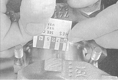
15. Using the flattened wire width measured against the scale printed on the Plastigage kit packaging, determine the bearing operating clearance. Compare the measurement with the Specifications.
16. If the clearance is outside the acceptable range, before looking for a different size bearing, check that no dirt/oil has gotten under the backs of the bearings in the connecting rod and cap. Measure the journal diameter again. If the wire is flattened more at one end than the other, the journal is tapered.
Final installation of the connecting rod and piston assembly
1. Using your fingernail or the edge of an old credit card, carefully scrape off any traces of gauge wire from the journal and/or bearing surface.
2. Make sure both bearing surfaces are absolutely clean, then lubricate them evenly with a thin layer of molybdenum-containing engine assembly grease. To gain access to the surface of the upper bearing, you will have to push the piston into the cylinder a little - do not forget to put protective hoses on the connecting rod cap bolts to avoid damaging the surface of the shaft journal. Try to prevent the piston rings from jumping out of the cylinder.
3. Return the connecting rod to its place by carefully placing its lower head on the journal of its crank, remove the protective hoses from the bolts, install the cover, and tighten the fastening nuts to the required force in three stages.
Note: Make sure that the marks on the connecting rod cap and its lower head are correctly aligned.
4. Repeat the entire procedure for the remaining connecting rod and piston assemblies.
5. Don't overlook the following important points:
- a) Make sure that no dirt gets on the backs of the bearings and their beds in the connecting rods and caps;
- b) Make sure that each assembly is installed in its own cylinder (even if new components are installed, since the piston ring clearances were adjusted to specific cylinders);
- c) The pistons must be positioned with the mark/arrow on their bottom forward along the engine (towards the timing drive);
- d) Do not forget to lubricate the cylinder bores with engine oil before installing the assemblies;
- e) Do not forget to lubricate the bearings (after checking the working clearances in the latter) before final installation of the covers.
6. After completing the installation of the connecting rod and piston assemblies, check the freedom of rotation of the crankshaft by turning it several times by hand.
7. Finally, it is necessary to check the axial play of the crankshaft once again (see Section Removal connecting rod and piston assemblies).
8. Compare the results of the end play measurement with the requirements of the Specifications. If the play was normal before disassembling the engine and the old connecting rod and piston assemblies were used, there should be no surprises. If the play value goes beyond the permissible limits after replacing the connecting rods, the latter must be removed from the engine and sent to a car service workshop for appropriate mechanical treatment.