
2. Determine the presence of cracks, corrosion, deposits. Inspect the condition of the threads. If the detected defects cannot be repaired. Replace the block.
3. Inspect the cylinder walls for scoring and metal galling.
4. Measure the diameter of each cylinder at the stop zone of the upper compression ring, then at the middle of the stroke and at the bottom. Note: the block must stand on a level surface during measurements.
Take measurements first along the diameter parallel to the crankshaft axis, then in the direction perpendicular to the axis.
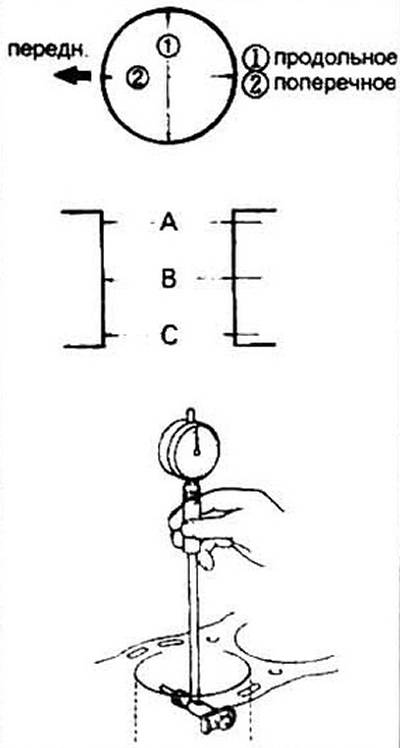
Fig. 15.4 Top. Cylinder diameter measurement locations: A - upper ring stop zone at TDC; B - middle of the stroke; C - bottom of the cylinder.
Below: Measuring diameter with a telescopic gauge. Use a micrometer to determine the true diameter value.
5. Compare the measurement results with the specification data.
6. If you do not have sufficiently accurate measuring equipment to perform this work, you can measure the piston/sleeve clearance in another, but less accurate way, namely, using a flat feeler gauge.
7. To perform the work, you will need a feeler gauge of the required thickness, corresponding to the required clearance, approximately 300 mm long. Place the feeler gauge along the cylinder wall, perpendicular to the crankshaft axis.
8. The piston should move in the cylinder with medium force.
9. If the piston falls or moves with little force, the clearance is too large and a new piston is required. If the piston bites at the bottom of the sleeve and comes out freely through the top, the cylinder is worn.
10. Repeat all measurements for the remaining cylinders.
11. If there is metal galling or scoring on the cylinder walls, or if the wear of the walls is beyond acceptable limits, the block should be bored and honed. After boring, a piston group of repair size must be installed.
12. If the condition of the walls is considered good and the wear does not exceed the permissible limits, it is sufficient to simply apply a hone mesh (see item 16).
13. Repair sizes of pistons are produced larger than the nominal size by 0.25 mm and 0.5 mm.
14. Measure the warpage of the block mating surface from the head side. If the warpage is beyond the permissible limits, it is necessary to restore the surface using machine processing.
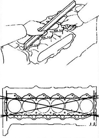
Fig. 15.14 Top. Measuring block warpage with a plane-parallel block and feeler gauge.
Below. Direction of warpage measurements