
2. Place the block with the crankshaft bed facing up.
3. Remove the main bearing caps and place them side by side in strict order. Do not mix up the caps.
4. Wipe the seats in the shaft bed and bearing caps. The wiping cloth should be lint-free.
Main bearing clearance check
5. Wipe the back of the liners and insert them into the bed and covers, making sure that the liners' clips fit into the corresponding slots.
Caution: Check the alignment of the oil holes in the block and the bearing. Do not use a hammer or other impact tools when installing the bearings. Do not lubricate the bearing at this stage.
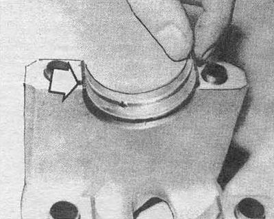
Fig. 22.5 Ensure that the bearing retainer is installed correctly. Check that the oil holes are aligned
6. Install the axle bearing into the center main bearing cap.
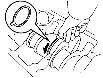
Fig. 22.6a Install the lower half ring of the axial bearing on the central journal of the shaft with the oil grooves facing outward. To facilitate their installation in place, rotate the shaft
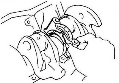
Fig. 22.6b Axial bearing in the center journal cover. Install oil grooves outward
7. Wipe the crankshaft journals with a lint-free cloth.
8. Check the shaft oil passages for dirt.
9. Carefully insert the shaft into the bed. Do not rotate the shaft during the clearance measurement procedure.
10. The method for determining the bearing clearance is described below.
11. Cut pieces of plastic gauge slightly shorter in length than the width of the bearing. Place the pieces of gauge on each main journal parallel to the crankshaft axis.
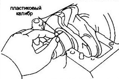
Fig. 22.11 Position of the plastic gauge on the neck for measuring the gap
12. Install the bearing caps. Pay attention to the presence of guide pins. Try not to move the gauges.
13. Tighten the main bearing caps, working from the center outward in three steps to the specified torque.
14. Loosen the bearing cap bolts and remove the caps. If there is difficulty in removing the caps from the block bed, you can use light blows with a soft-surface hammer.
15. Measure the width of the gauges using the scale on the packaging. Compare the obtained data with the recommended specifications.
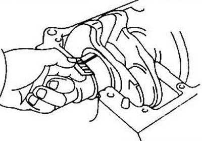
Fig. 22.15 Measuring the gap by gauge thickness. Measure the gap at the widest point. Pay attention to the scale scale (inches or millimeters)
16. If the bearing clearance is unsatisfactory, replace the bearing shell with another of the next standard size. Check your dimensions again before replacing the bearing shell (see item 18).
17. Carefully remove the remaining gauges from the neck. Do not damage the surfaces.
Final shaft installation
Note: Install pistons with connecting rods first (see section 24), then you can install the main bearing caps.
18. Remove the shaft from the engine.
19. Wipe the bearing surfaces of the liners, lubricate them and insert the liners into place. Lubricate the bearing surfaces of the bearings. Pay attention to the correct orientation of the axial bearing.
20. Place the shaft into the block.
21. Lubricate the bearings in the cover.
22. Install the main bearing caps, do not forget about the axle bearing.
Note: Replace the rubber ring in the center main bearing cap where the oil bridge connects (in engines where it is present).
23. Tighten the cover bolts by hand.
24. Tighten the bolts from the center to the periphery in three stages to the torque specified in the specification.
25. On models with manual transmission, check the presence of support bearing 8 at the rear of the crankshaft.
26. Turn the shaft several times by hand.
27. Check the axial clearance (see section 13).
28. Install the rear oil seal.