
Note: Before removing the piston/connecting rod assembly, remove the cylinder head and oil pan. Refer to Part A of Chapter 2 for the necessary information.
1. Use your finger to check for a protrusion in the stop zone of the upper compression ring (about 8 mm down from the cylinder cut). If the protrusion is formed by coke deposits, remove them with a scraper or special tool. Careless or incomplete removal of the protrusion when dismantling the piston may result in damage to it.
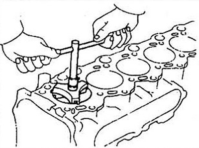
Fig. 12.1 Removing carbon deposits and protrusions from the top of the cylinder with a special tool before dismantling the pistons
2. After removing the tabs, turn the engine upside down with the crankshaft.
3. Check the axial clearance between the connecting rod and the crankshaft using a feeler gauge. If the clearance exceeds the permissible limit, replace the connecting rod. If a new connecting rod is installed (or crankshaft), then the clearance may become less than the permissible value. In this case, mechanical processing of the connecting rod is required.
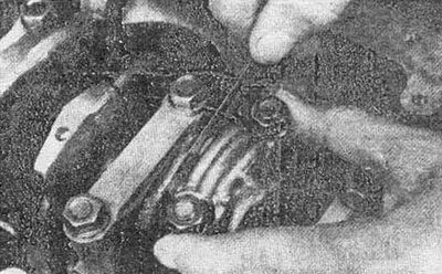
Fig. 12.3 Measuring the connecting rod-crankshaft clearance
4. Check for identification marks on the connecting rod and its cap (see fig. 12.4a). If there are no marks, make marks using a punch. An example of marking the fourth connecting rod is shown in Fig. 12.4b.
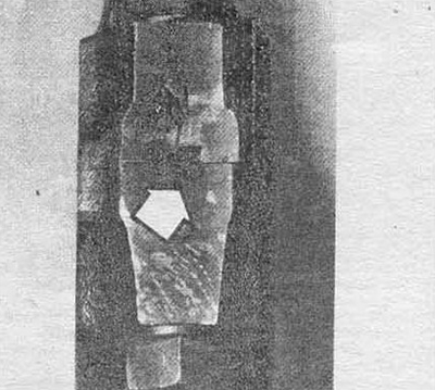
Fig. 12.4a Markings applied to the connecting rod (shown by arrow) are not the serial number of the connecting rod. This is the code for the internal diameter of the connecting rod bearing bed
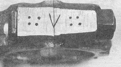
Fig. 12.4b Punch the connecting rod serial number with a punch
5. Loosen the connecting rod cap nuts in ½ turn increments. Remove the connecting rod cap together with the bearing shell. Do not remove the bearing shell from the cap.
6. To avoid damaging the crankshaft surfaces and cylinder walls, place protective pieces of plastic or rubber tube on each connecting rod bolt.
7. Remove the upper connecting rod bearing and push the piston out of the cylinder. Use a block of hard wood or the handle of a hammer to do this. If the piston does not come out of the cylinder, check again whether the protrusion at the top of the cylinder has been completely removed.
8. Repeat steps 3-7 for all connecting rods.
9. Put the connecting rod caps back in place and tighten the nuts onto the connecting rod bolts. Remove the bearing shells and store them in a place that will prevent damage to the bearing surfaces.
10. Do not remove the piston from the connecting rod (for more information, please see section 17).
(Full version on the source website HondaBook)