
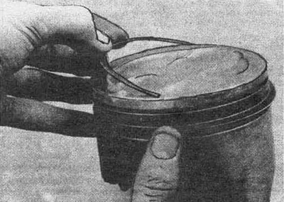
2. The method of measuring the gaps in the lock of the rings is described below.
3. Insert the ring into the cylinder and push it with the piston to the position corresponding to the stop of the ring at bottom dead center.
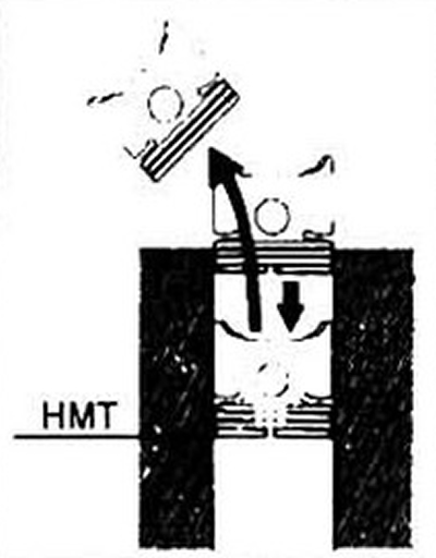
Pic. 21.3 To check the gap in the lock of the ring, push it with the piston to the BDC position
4. Use a flat feeler gauge to measure the lock clearance. The feeler gauge should slip with little force. Compare measurement results with specification data.
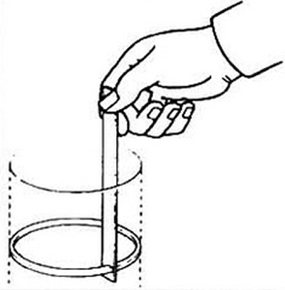
Pic. 21.4 Measuring the gap in the lock
5. A small gap in the lock can lead to breakage of the ring during normal engine operation. You can increase the gap with a file. Secure the file in a vise, press down and slowly file the ring.
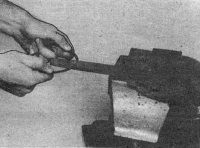
Pic. 21.5 Correction of a small gap. Use a single cut file
6. Remember that the critical gap in the lock is 1 mm.
7. Repeat steps 2-6 for all rings.
8. Install the rings in their respective piston positions.
9. Install the oil scraper ring first. It usually consists of three components. Install expander (see fig. 21.9a) into the groove if the ring design uses a rotation lock. insert it into the hole in the piston groove, then install the guide. When assembling the oil scraper ring, do not use a ring remover, work with your hands. Press the guide firmly against the groove and rotate it until it is fully seated, do the same with the top guide.
Pic. 21.9a Installing the oil scraper ring expander
Pic. 21.9b Do not use a ring remover to install oil scraper ring guides
10. Check up ease of rotation of both guides in a piston flute.
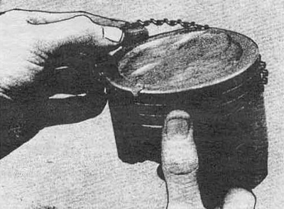
11. Install the second, then the first ring on the piston. Do not confuse them in places: they have different sections. The orientation of the rings is indicated on their side surface.
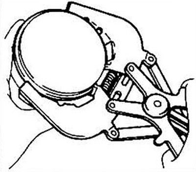
Pic. 21.11 Fitting the compression rings with a puller