
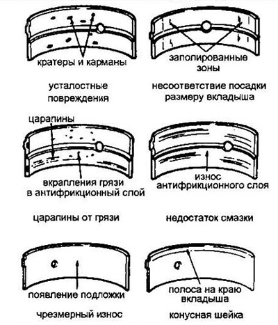
Pic. 19.1 Typical pictures of bearing damage
2. Bearing damage occurs due to lack of lubricating oil, dirt and other foreign particles, motor overload and corrosion. Regardless of the cause of bearing failure, it must be identified and corrected prior to engine reassembly.
3. To inspect the bearings, lay them on a flat and clean surface in the same order as they are on the engine. This is necessary in order to correctly identify the main or connecting rod journals that have defects.
4. Dirt and other foreign particles can enter the engine in various ways: during assembly, through filters or the crankcase ventilation system. Solid particles damage the surface of the bearings. Large foreign particles cannot be removed by the oil and gouge the bearing and the shaft journal. The best protection against such damage is a clean assembly and frequent filter replacement.
5. Lack of lubricant flow through the bearings can be caused by a number of interrelated reasons, such as overheating of the motor (oil viscosity reduction), overload (squeezing oil out), excessive leakage through the bearing with a large gap in it, wear of the oil pump and frequent operation at high speeds. Rarely, but there is a mechanical blocking of the oil channels due to a mismatch between the holes in the block and in the bearing.
Lack of lubrication results in abrasion or displacement of the anti-friction coating of the liners, and local heating can cause tint colors to appear on the steel substrate of the liner.
6. Bearing life is also affected by riding style. Slow speed travel at full throttle (those. untimely shifting to a higher gear) results in overloading of the bearings and tends to thin the carrier oil layer. Such loads strongly bending the bearing lead to the appearance of a network of fatigue cracks. At the same time, the anti-friction layer may crumble. Frequent trips over short distances lead to corrosion of the bearings (condensation of moisture and corrosive gases on unheated massive parts) Condensation products accumulate in the mass, forming a fairly significant amount of acids.
7. Dirty assembly, excessive force when assembling the bearing, incorrect orientation of the liners lead to quick and sure failure.
Rejection
8. If the bushings you removed are worn or damaged, or the bearing clearance is out of specification (see paragraphs 22 and 23) we offer below the following procedure for selecting new bearings. This procedure does not apply to the case of regrinding the shaft to the repair size - here the installation of repair liners is simply mandatory.
Main bearings
9. When setting the nominal bearing size, make sure the color code of the old and new bearing matches. The color code is printed on the edge of the liner.
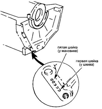
10. If the color code of the bearing is lost, it can be restored using the marks stamped on the block from the connection side of the clutch housing or the mating plane of the oil pan.
Pic. 19.10 Codes for the dimensions of the diameters of the crankshaft beds (letters)
11. The location of the main bearing diameter codes is shown in Figure 19.11.
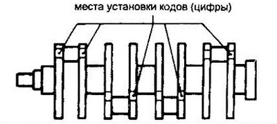
Pic. 19.11 Crankshaft journal size codes
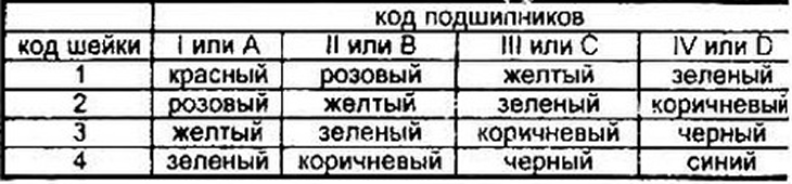
12. Select bearings according to the table in fig. 19.12.
Pic. 19.12 Selection of a bearing color code using a buoy or Roman numerals on the block and Arabic numerals on the crankshaft. For example: the combination of C3 gives brown.
Horizontal arrow: decrease in liner thickness, increase in shaft bed diameter.
Vertical arrow: reduction of the neck, reduction of the thickness of the liner.
Connecting rod bearings
13. Pay attention to the color code when installing a nominal size insert.
14. If the color code of the old bearing is lost, seek help from the side of the connecting rod bearing cap.
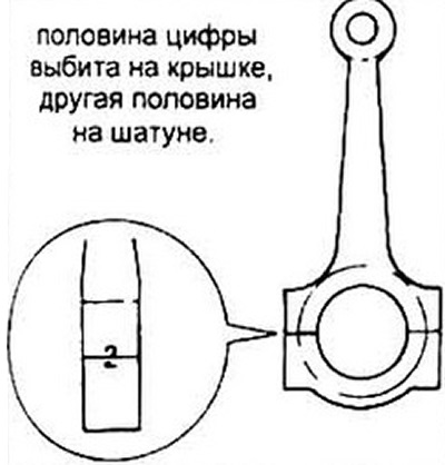
Pic. 19.14 Connecting rod bearing hole size code. Is not a serial number of the connecting rod
15. In fig. 19.15 you will find the places for setting the diameter code of the corresponding crankpin (keep in mind that these are not neck numbers).
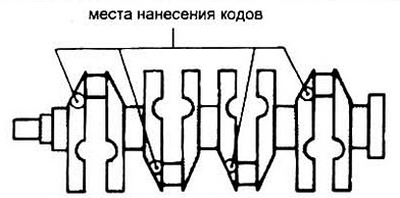
Pic. 19.15 Crankpin size codes (letters)
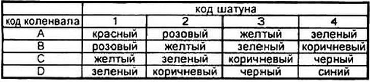
16. According to the table in fig. 19.16 determine the color code of the loose leaf for each connecting rod neck.
Pic. 19.16 Search for the required connecting rod bearing code using the numbers on the connecting rod and the letters on the shaft. Example D4 is blue.
Horizontal arrow: increase in the diameter of the connecting rod, refined bushing.
Vertical arrow: reduction of the neck diameter, thinning of the liner.
All bearings
17. Remember that the final choice of bearing size is determined by the clearance in the bearing.
18. Note After assembling the engine with new bearings, the engine should be warmed up at idle to operating temperature and run in this mode for 15 minutes.