
Contents: Removal ⇊ Disassembly, inspection, cleaning…⇊ Checking the VTEC rocker arm assembly ⇊ Disassembling and assembling the…⇊ Rocker arm axles (models without…⇊ Installation ⇊
Removal
Note:
- To avoid warping of the cylinder head, do not remove it when the coolant temperature is above 38V.
- Label all wires and hoses before disconnecting. Make sure they do not come into contact with other wires, hoses or components.
1. Before carrying out any work, turn off the vehicle's security system.
2. Disconnect the cable from the negative terminal of the battery.
3. Drain the coolant.
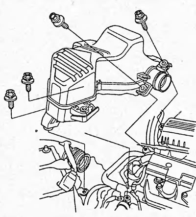
4. Remove the intake resonator.
5. Remove the throttle cable (B) by loosening the lock nut (A) and pull it out of the brackets.
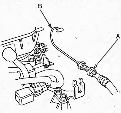
Caution: Do not bend the cable. If the cable is bent, it must be replaced.
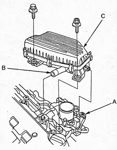
6. Disconnect the intake air temperature sensor connector (A), remove the intake hose (B), and remove the air filter (C).
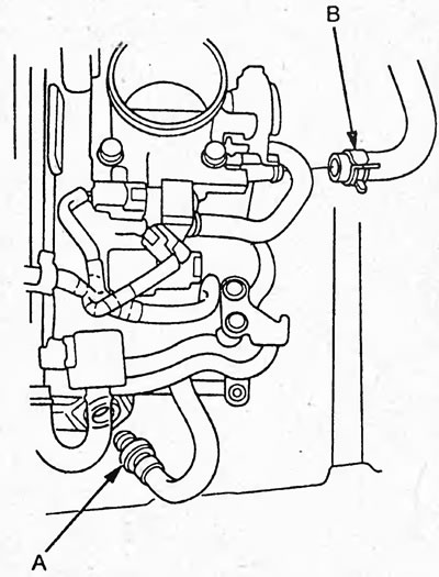
7. Remove the vacuum booster hose (B) and the positive crankcase ventilation hose (A).
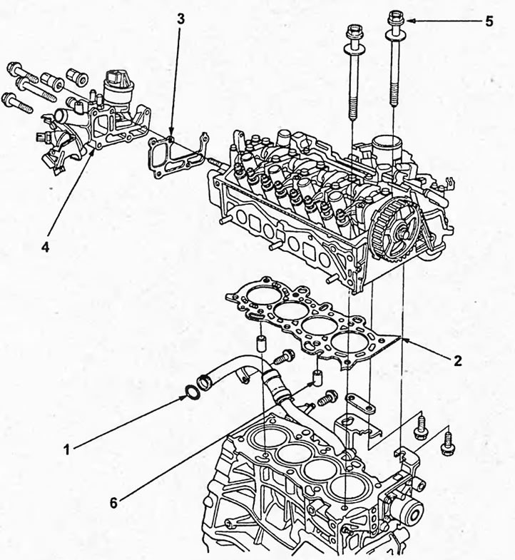
Removal and installation the cylinder head. 1 - sealing ring, 2 - cylinder head gasket, 3 - gasket, 4 - cooling system adapter, 5 - cylinder head mounting bolts, 6 - dowel pin.
8. Reduce the pressure in the fuel system.
9. Disconnect the fuel vapor canister hose.
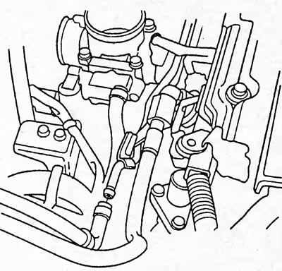
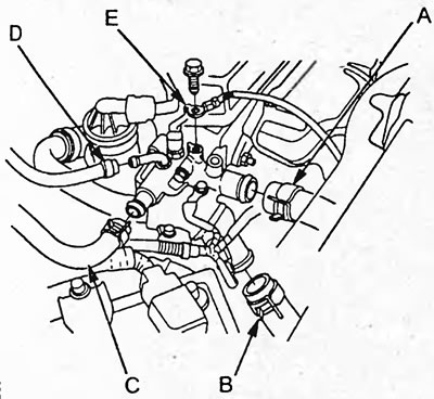
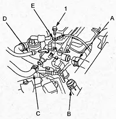
10. Remove the ground wire (E), upper (A) and lower (B) radiator hoses, interior heater hose (C) and coolant bypass hose (D).
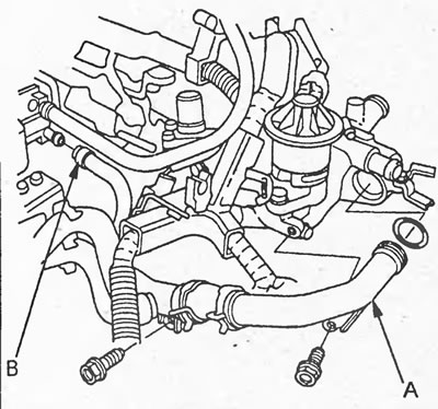
11. Loosen the two cooling system pipe mounting bolts, disconnect the cooling system pipe (A) and the cooling system bypass hose (B).
12. Disconnect the connectors of the following sensors and valves by disconnecting the clamps, then remove the wiring harness.
- Throttle position sensor connector.
- Manifold Absolute Pressure Sensor Connector.
- Injector connectors.
- Coolant temperature sensor connector.
- Cooling system fan switch connector.
- Oxygen sensor connector.
- (D17A) Valve connector for variable valve timing and lift Height (VTEC) systems.
- (D17A) VTEC oil pressure sensor connector.
- Engine oil pressure sensor connector.
- (D15B) Fuel mixture sensor connector.
13. Jack up the engine. Place a wooden block between the jack foot and the engine.
Note: Do not place the jack in the center of the oil pan to avoid damaging the pan.
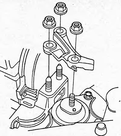
14. Remove the upper engine mount bracket.
15. Remove the exhaust manifold heat shield (A) and the exhaust manifold (B).
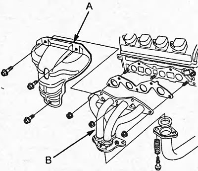
Type 1.
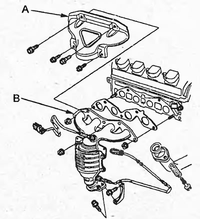
Type 2.
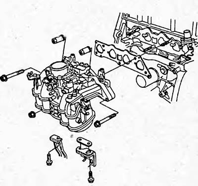
16. Remove the intake manifold.
17. Remove the ignition coils and cylinder head cover (see section "Checking and adjusting thermal clearances in the valve drive").
18. Remove the timing belt (see section "Timing belt").
19. Remove the camshaft toothed pulley by unscrewing the mounting bolt and remove the rear cover.
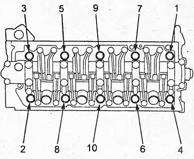
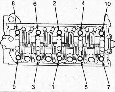
20. Loosen the cylinder head mounting bolts. To prevent warping of the cylinder head, loosen the bolts alternately by 1/3 turn per pass in the sequence shown in the figure.
21. Remove the cylinder head.
22. Remove the VTEC rocker arm assembly and camshafts.
a) Loosen the adjusting nuts (A).
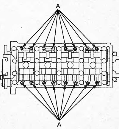
b) Loosen the camshaft bearing cap mounting bolts in 2 passes in the sequence shown in the figure.
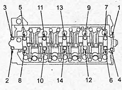
c) Remove the camshaft bearing caps and the camshaft.
d) Remove the VTEC rocker arm assembly.
Disassembly, inspection, cleaning and repair of the cylinder head
The procedures for disassembling, checking, cleaning, repairing and assembling the cylinder head components are discussed in the chapter "Engine - General Repair Procedures".
Checking the VTEC rocker arm assembly
Note: The test is performed on the vehicle. Before testing, set the piston of cylinder #1 to TDC.
a) Check that the secondary intake rocker arm (A) moves independently of the main intake rocker arm (B).
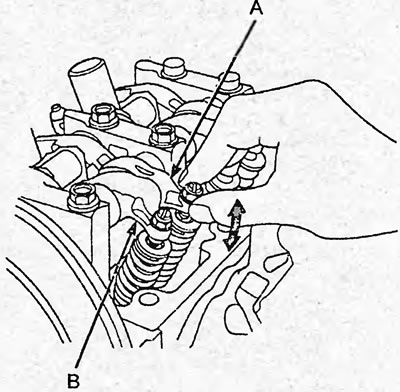
If the secondary rocker arm does not move freely, remove the primary rocker arm and secondary rocker arm assembly and check that the timing pin rotates smoothly. Replace the primary and secondary rocker arm assemblies if necessary.
b) Check all rocker arms in the manner described above, setting the piston of each cylinder to TDC.
c) Cover the timing belt to prevent dirt from getting on it.
d) Install a special device into the hole to reduce pressure.
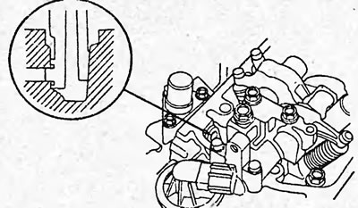
d) Loosen and remove the plug bolt (A) from the inspection hole (B) and connect the special tool to the hole.
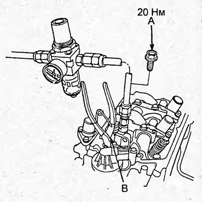
e) Apply a pressure of 250 kPa.
Note: If the timing pins do not rotate after increasing the pressure, turn the crankshaft counterclockwise to make the main and sub rocker arms start moving.
g) Move the secondary rocker arm (A) of cylinder No.1. The primary (B) and secondary rocker arms should move together.
If the primary rocker arm does not move freely, remove the primary rocker arm and secondary rocker arm assembly and check that the timing pin rotates smoothly. Replace the primary and secondary rocker arm assemblies if necessary.
h) Remove the special tools and install the plug bolt and camshaft.
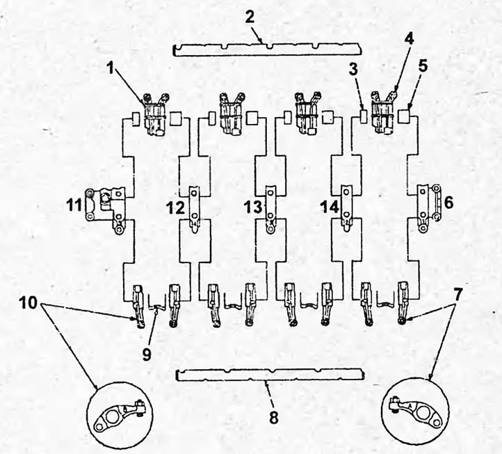
VTEC system rocker arm block. 1 - rubber, 2 - exhaust valve rocker arm shaft, 3 - seal "B", 4 - exhaust valve rocker arms, 5 - seal "A", 6 - camshaft bearing cover No.1, 7 - intake valve rocker arms "A", 8 - intake valve rocker arm shaft, 9 - spring, 10 - intake valve rocker arms "B", 11 - camshaft bearing cover No.5, 12 - camshaft bearing cover No.4, 13 - camshaft bearing cover No.3, 14 - camshaft bearing cover No.2.
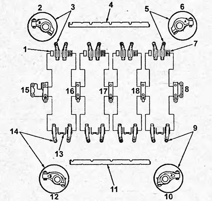
Rocker arm axles. 1 - seal, 2, 6, 10, 12 - mark, 3 - intake rocker arms "B", 4 - intake rocker arm shaft, 5 - intake rocker arms "A", 7 - spring, 8 - camshaft bearing cover No.1, 9 - exhaust rocker arms "A", 11 - exhaust rocker arm shaft, 13 - spring, 14 - exhaust rocker arms "B", 15 - camshaft bearing cover No.5, 16 - camshaft bearing cover No.4, 17 - camshaft bearing cover No.3, 18 - camshaft bearing cover No.4.
Disassembling and assembling the VTEC rocker arm unit
Note:
- When disassembling the VTEC rocker arm assembly, stack the parts in the order they were removed for subsequent installation in their proper place.
- When removing the rocker arms, do not loosen the camshaft bearing cap mounting bolts.
- Before assembly, clean all parts with solvent and apply a layer of grease to the contact surfaces.
- When assembling the rocker arms, apply a layer of engine oil to the surfaces of the timing pins.
- After assembling the rocker arms, secure them with a rubber band.
Rocker arm axles (models without VTEC system)
The notes described in the subsection "VTEC Rocker Arm Block" are also valid for this subsection.
Installation
Note:
- Before installation, wipe the timing belt pulleys and covers with a rag.
- The cylinder head gasket is made of metal, do not allow it to bend.
- Check the bolt washers, replace any worn or damaged ones.
The installation of the head and cylinder block is carried out in the reverse order of removal.
1. Install the VTEC rocker arm assembly, camshaft and camshaft sprocket.
a) Clean the camshaft journals and cylinder head bearings, then apply a layer of oil to the cleaned surfaces.
b) Clean and install the oil bypass valve (A) with a new sealing ring (B). Turn the camshaft so that the keyway (C) is facing upwards.
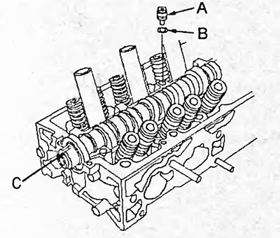
c) Loosen the adjusting nuts.
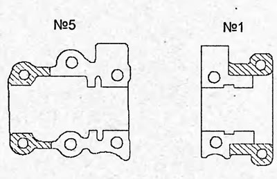
d) Apply a layer of sealant to camshaft bearing caps No.1 and No.5 as shown in the figure.
Note: The parts must be installed within the time specified in the sealant application instructions. Otherwise, the sealant must be removed and reapplied.
d) Install the VTEC rocker arm assembly in the desired position and tighten the mounting bolts.
Note: Make sure the rocker arms are seated properly on the valves.
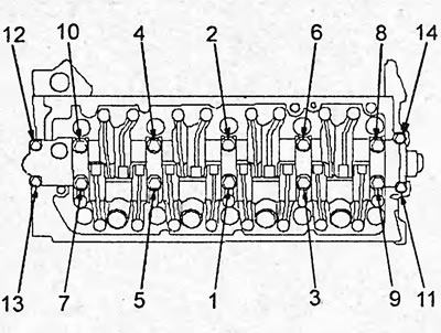
e) Tighten the camshaft bearing cap bolts in 2 passes in the sequence shown in the figure.
Note: Apply a layer of engine oil to the bolt threads. The 06mm bolts are marked with numbers in the figure "11", " 12", "13", "14".
Tightening torque:
- bolts 08 mm - 20 Nm
- bolts 06 mm - 12 Nm
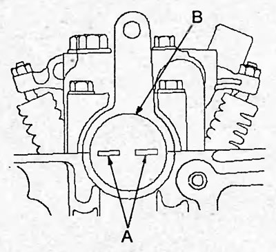
g) Install the plug (B) on the cylinder head so that the marks (A) on the plug lie in the plane of the cylinder head.
h) Install the rear timing belt cover, camshaft toothed pulley and tighten the mounting bolts.
Tightening torque:
- cover mounting bolts - 10 Nm
- pulley mounting bolt - 37 Nm
2. Clean the surface of the cylinder head and cylinder block.
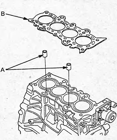
3. Install a new cylinder head gasket (B) and dowel pins (A) onto the cylinder block.
Note: Always use a new cylinder head gasket.
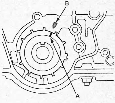
4. Align the mark (A) on the timing belt drive pulley with the reference mark (B) on the oil pump.
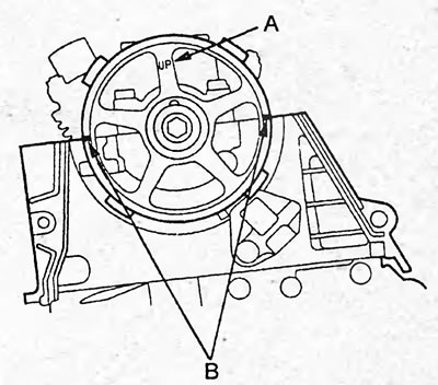
5. Set the piston of the first cylinder to TDC. In this case, the "UP" mark (A) on the camshaft pulley should be directed upwards, and the TDC marks (B) should lie in the plane of the cylinder head.
6. Place the cylinder head on the cylinder block.
7. Apply fresh engine oil to the threads and under the bolt heads.
8. Tighten the cylinder head bolts in the sequence shown in the figure. Do not overtighten the bolts. If a bolt makes noise when tightening, remove it and retighten it.
Tightening torque:
- stage 1 - 20 Nm
- stage 2 - 49 Nm
- stage 3 - 67 Nm
9. Install the timing belt (see section "Timing belt").
10. Adjust the thermal clearance in the valve drive.
11. Install the cylinder head cover (see section "Checking and adjusting thermal clearances in the valve drive").
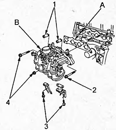
12. Install a new gasket (A), intake manifold (B), tighten the mounting bolts and nuts crosswise in 2-3 passes, starting with the inner nuts. Install the intake manifold brackets and tighten the mounting bolts.
Tightening torque:
- bolts and nuts "7", "2" "4" — 22 Nm
- bolts "3" - 12 Nm
13. Install the exhaust manifold (B) with a new gasket (A) and tighten the new mounting nuts. Install the heat shield (C) and tighten the mounting bolts. Tighten crosswise in 2-3 passes.
Tightening torque:
- bolts "1" and nuts "3" - 31 Nm
- bolt "4" - 24 Nm
- bolt "2" - 22 Nm
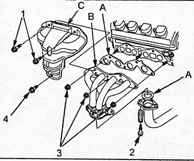
Type 1.
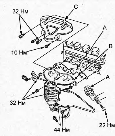
Type 2.
14. Connect the exhaust pipe with a new gasket and the exhaust manifold bracket.
15. Install the coolant pipe (B) with a new sealing ring (C). Install the coolant bypass hose (A).
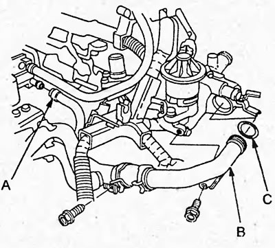
16. Install the ground wire (E) and tighten the mounting bolt. Install the upper (A) and lower (B) radiator hoses, the heater hose (C) and the coolant bypass hose (D).
Tightening torque - 10 Nm
17. Install the fuel hoses.
18. Install the fuel vapor canister hose.
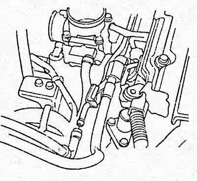
19. Connect the brake booster hose (B) and the positive crankcase ventilation hose (A).
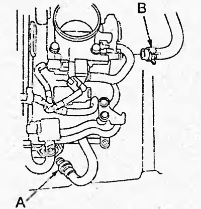
20. Install the air filter (A), connect the intake air temperature sensor connector (B) and connect the drain hose (C).
Tightening torque - 12 Nm
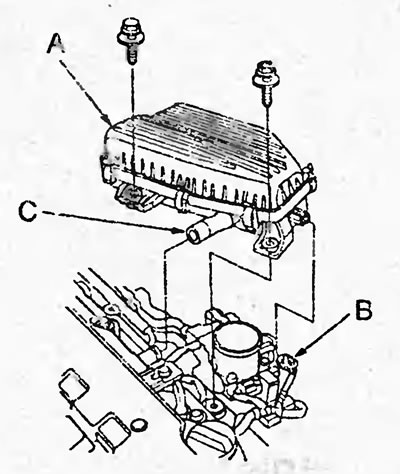
21. Install the intake resonator.
Tightening torque - 12 Nm
22. Install the throttle cable, cruise control cable (cruise control) and adjust them.
23. Connect the connectors to the sensors and valves specified in step 15.
24. Connect the wire to the negative terminal of the battery.
25. Make sure all tubes and connectors are connected correctly.
26. Check for fuel leaks.
Turn the ignition key to the "ON" position (do not start the engine) so that the fuel pump runs for 2 seconds and increases the pressure in the fuel line. Repeat this operation 2-3 times and check the fuel line for fuel leaks.
27. Fill with coolant and bleed air.
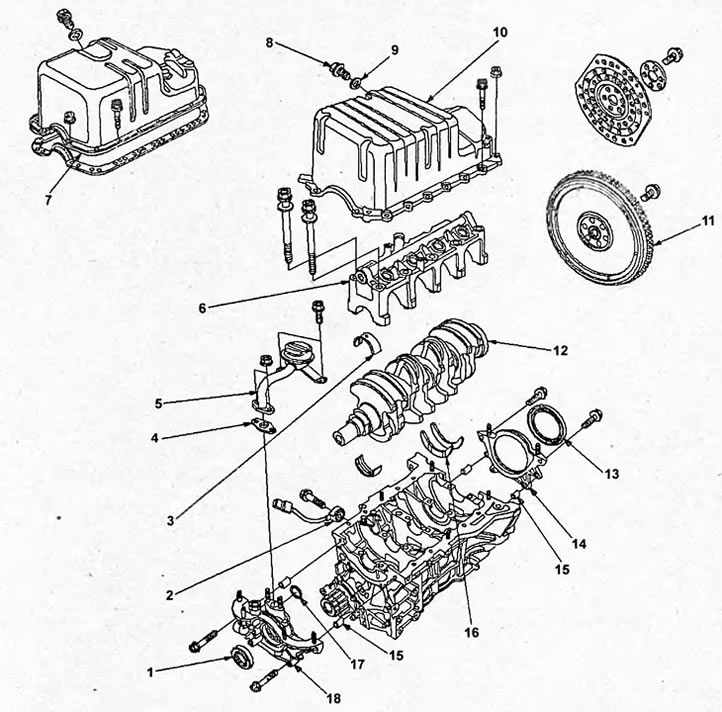
Disassembly and assembly of the cylinder block. 1 - front crankshaft oil seal, 2 - knock sensor, 3 - crankshaft main journal bearing shell, 4 - gasket, 5 - oil receiver, 6 - main bearing cap, 7 - oil pan (models with steel oil pan), 8 - drain bolt, 9 - washer, 10 - oil pan (models with aluminum oil pan), 11 - flywheel, 12 - crankshaft, 13 - crankshaft rear oil seal, 14 - crankshaft rear oil seal holder, 15 - dowel pin, 16 - thrust half rings, 17 - sealing ring, 18 - oil pump.
(Full version on the source website: «Hondabook.ru»)