
Note: Checking clearances should be carried out at engine temperature of 10 - 40°C.
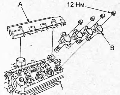
1. Remove the ignition coil cover (A) and remove the ignition coils (B).
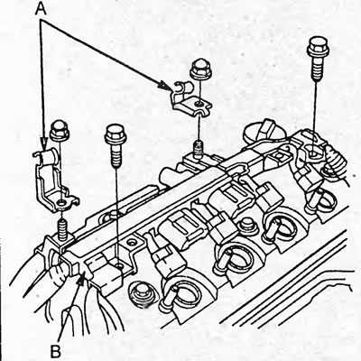
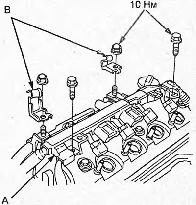
2. Remove the throttle cable brackets (A) and wire harness bracket (B) from the cylinder head cover.
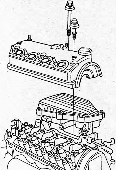
3. Remove the cylinder head cover.
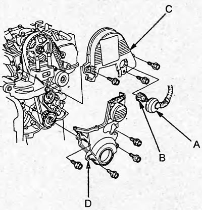
4. Remove the seal (A) and disconnect the camshaft position sensor connector (B) from the upper timing belt cover as shown in the figure below.
5. Remove the upper (C) and lower (D) timing belt covers.
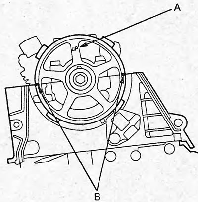
6. Set the piston of the first cylinder to TDC. In this case, the "UP" mark (A) on the camshaft pulley should be directed upwards, and the TDC marks (B) should lie in the plane of the cylinder head.
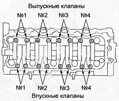
7. Select the appropriate feeler gauges to measure the valve clearance.
Feeler gauge for measuring clearances in the drive:
- intake valves - 0.18 - 0.22 mm
- exhaust valves - 0.23 - 0.27 mm
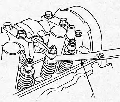
8. Insert the feeler gauge (A) between the adjusting screw and the end of the valve. Move the feeler gauge back and forth until a slight resistance is felt.
9. If there is a lot of resistance or no resistance, loosen the lock nut (A) and adjust the clearance with the adjusting screw.
Gap:
- intake valves - 0.18-0.22 mm
- exhaust valves - 0.23-0.27 mm
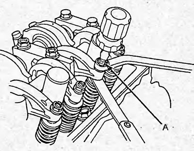
D15B models without VTEC system.
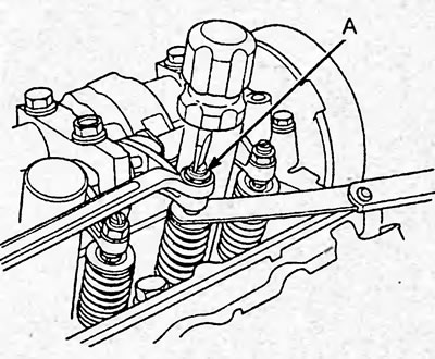
Rest.
10. Tighten the lock nut and recheck the clearance. Adjust it if necessary.
Tightening torque:
D15B models without
- vTEC systems - 18Nm
- The rest are 20 Nm
11. Set the piston of the third cylinder to TDC. In this case, the "UP" mark on the camshaft pulley should be directed as shown in the figure.
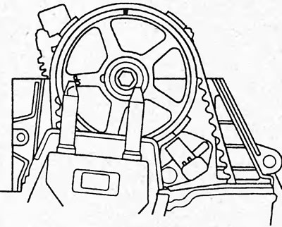
12. Check and, if necessary, adjust the clearance in the valve drive of the third cylinder.
13. Set the piston of the fourth cylinder to TDC. In this case, the "UP" mark on the camshaft pulley should be directed as shown in the figure.
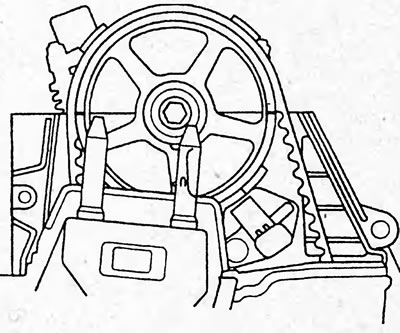
14. Check and, if necessary, adjust the clearance in the valve drive of the fourth cylinder.
15. Set the piston of the second cylinder to TDC. In this case, the "UP" mark on the camshaft pulley should be directed as shown in the figure.
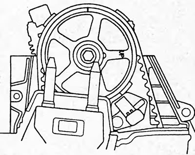
16. Check and, if necessary, adjust the clearance in the valve drive of the second cylinder.
17. Install the cylinder head cover.
a) Thoroughly clean the gasket and gasket groove of the cylinder head cover.
b) Install the gasket into the cover.
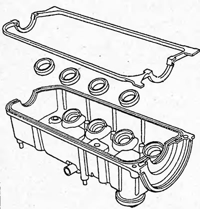
c) Make sure that the contact surfaces are clean and dry.
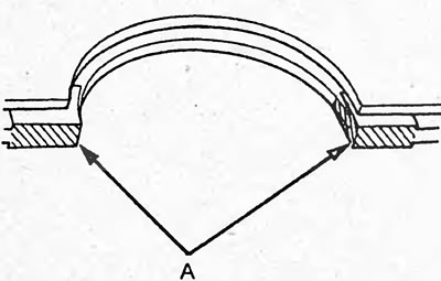
d) Apply a layer of sealant to the cylinder head cover, at the locations (A) shown in the figure.
Note: The parts must be installed within the time specified in the sealant application instructions. Otherwise, the sealant must be removed and reapplied.
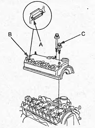
d) While holding the cylinder head cover gasket in position, install the spark plug seals (A). Then install the cylinder head cover (B). Move the cover back and forth to install the gasket.
e) Check the washers of the cover mounting bolts. Replace any damaged ones.
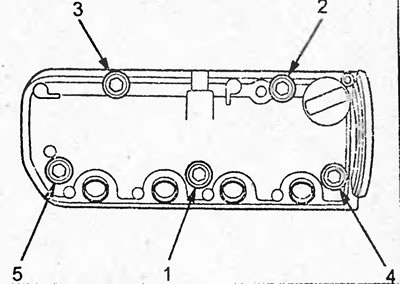
g) Tighten the bolts (C) in 2-3 passes in the sequence shown in the figure.
Tightening torque - 10 Nm
h) Install the wire harness bracket (A) and throttle cable brackets (B).
18. Installation of parts during assembly is carried out in the reverse order of removal.
[Publication reprinted from the website: www.hondabook.ru]