
Disassembly
1. Remove the camshafts.
2. Remove the VTEC rocker arm assembly.
3. Remove the tappets.
Note: Arrange the tappets in the order they are installed.
4. Remove the valves.
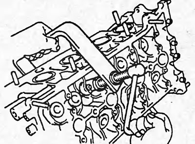
a) Using a suitable tool, compress the valve spring and remove the two crackers.
b) Remove the spring plate, spring and valve.
c) Using long-nose pliers, remove the valve stem seals.
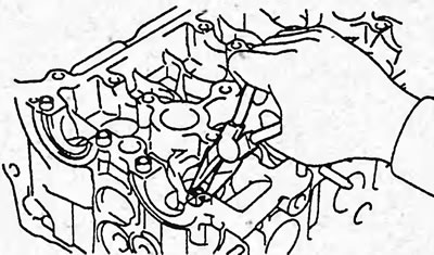
d) Remove the spring seat.
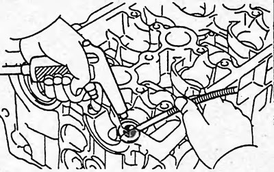
Note: Arrange the valves, springs, seats and spring retainers in the correct order.
Checking, cleaning and repairing
1. Clean the piston crowns and the cylinder block surface that mated with the cylinder head.
Turning the crankshaft, set the pistons in sequence to TDC. Use a scraper to clean the piston bottom surfaces from carbon deposits.
2. Clean the cylinder head.
a) Clean the cylinder head surface from any remaining gasket.
Note: Be careful not to damage the surface.
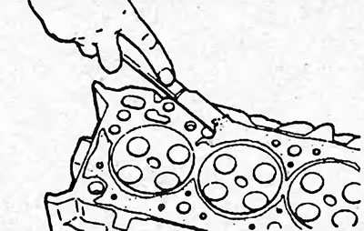
b) Clean the surfaces of the combustion chambers of the cylinder head with a wire brush, removing any remaining carbon deposits.
c) Clean the surface of the cylinder head (mating with the cylinder block surface), using a soft brush and solvent.
d) Clean the valve guide bores with a brush and solvent.
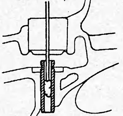
3. Using penetrating dye, check for cracks in the combustion chambers, intake and exhaust ports, and gas joint surfaces. If cracks are present, replace the cylinder head.
4. Check the axial and radial clearance of the camshaft bearings. If the clearances are greater than the permissible value, replace the camshaft.
5. Check the cylinder head. Using a precision ruler and a flat feeler gauge, as shown in the figure, check the non-flatness of the working surfaces of the cylinder head that are mated:
- with the cylinder block surface;
- with the surfaces of the intake and exhaust manifolds.
The maximum permissible non-flatness of the surface mating with the cylinder block surface is 0.05 mm
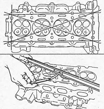
If the flatness value exceeds the maximum permissible value, replace the cylinder head or grind it.
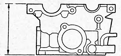
6. Check the height of the cylinder head.
Minimum height:
- D15B, D17A - 92.95 - 93.05 mm
- K20A - 103.95 - 104.05 mm
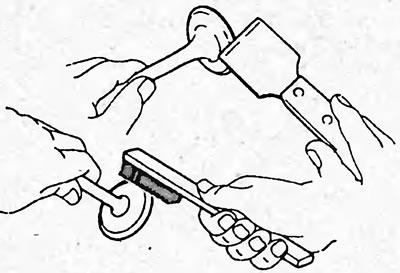
7. Clean the valves.
a) Use a scraper to remove carbon deposits from the valve plate.
b) Use a brush to finally clean the valve.
8. Check and grind the valves.
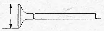
a) Check the valve plate width.
Nominal width:
D15B, D17A:
- inlet - 29.85 - 30.10 mm
- release - 25.90 -26.10 mm
K20A:
- inlet - 34.85 - 35.15 mm
- release - 29.85 - 30.15
b) Check the overall length of the valve.
Nominal length:
D15B, D17A:
- intake - 118.27 - 118.87 mm
- release - 115.65 - 116.25 mm
K20A:
- intake - 108.80 - 109.40 mm
- release - 108.40 -109.00 mm
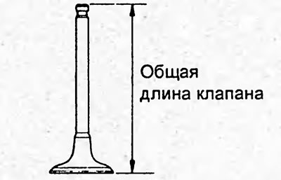
If the overall length is less than the minimum, replace the valve.
c) Check the condition of the end surface of the valves for wear.
If the valve end is worn, regrind the end or replace the valve.
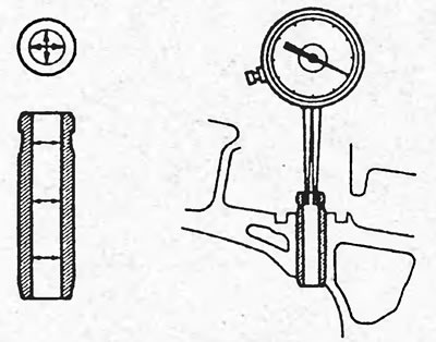
d) Using a bore gauge, measure the inner diameter of the valve guide bushings at three levels and two planes.
Diameter:
- nominal - 5.51 - 5.53 mm
- maximum - 5.55 mm
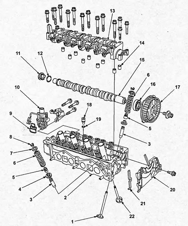
Disassembly and assembly of the cylinder head (D15B, D17A). 1 - intake valve, 2 - cylinder head, 3 - guide sleeve, 4 - spring seat, 5 - valve stem seal, 6 - valve spring, 7 - spring retainer, 8 - crackers, 9 - VTEC valve filter, 10 - VTEC valve, 11 - plug, 12, 19 - sealing ring, 13 - VTEC rocker arm assembly, 14 - bolt guides, 15 - camshaft, 16 - camshaft oil seal, 17 - camshaft toothed pulley, 18 - oil bypass valve, 20 - timing belt rear cover, 21 - rubber seal, 22 - exhaust valve.
d) Using a micrometer, measure the diameter of the valve stem at three levels and two planes.
Nominal valve stem diameter:
D15B, D17A:
- intake - 5.480 - 5.490 mm
- release - 5,450 - 5,460 mm
K20A:
- intake - 5.475 - 5.485 mm
- release - 5,450 - 5,460 mm
Minimum valve stem diameter:
- inlet - 5.45 mm
- release - 5.42 mm
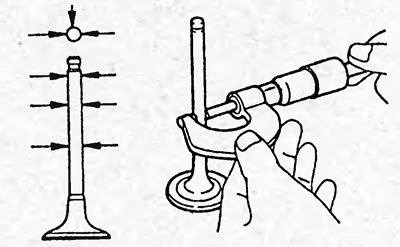
e) Measure the guide bush diameter in three places and the outside diameter of the valve stem in three places. Subtract the maximum guide bush diameter measurement from the minimum valve stem diameter. Calculate the clearance between the valve stem and the inside surface of the guide bush.
Nominal value:
D15B, D17A:
- inlet - 0.02 - 0.05 mm
- release - 0.05 - 0.08 mm
K20A:
- inlet - 0.030 - 0.055 mm
- release - 0.055 - 0.080 mm
Maximum value:
- inlet - 0.08 mm
- release - 0.11 mm
Replace the guide bushing if necessary.
9. Replace the valve guide if necessary.
a) Using a special tool, press out the guide bushing.
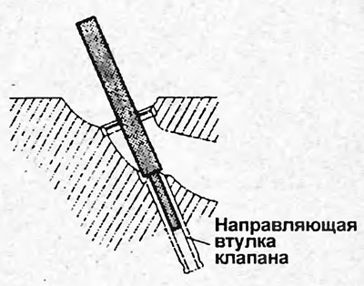
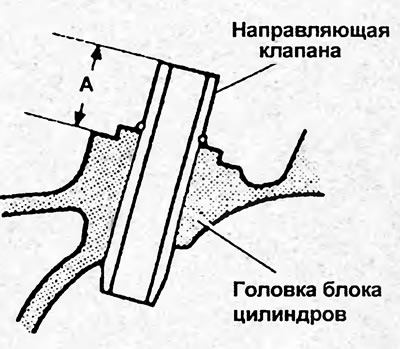
b) Using the special tool and a hammer, install the new valve guide bushing so that it protrudes from the cylinder head by the appropriate amount.
Valve guide bushing protrusion amount:
D15B, D17A:
- inlet - 17.85-18.35 mm
- release - 18.65-19.15 mm
K20A:
- inlet - 15.2-16.2 mm
- release - 15.5-16.5 mm
10. Check that the valve is seated correctly in the seat.
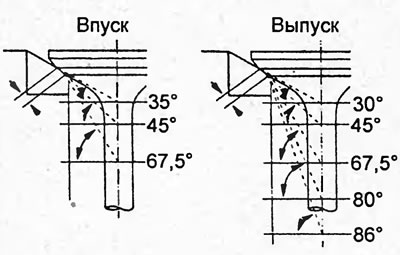
a) (D15B, D17A) Using carbide burs with the taper angles shown in the illustration below, grind the valve seats, removing only enough metal to clean the seat facets.
Normal chamfer width:
- inlet - 0.85- 1.15 mm
- release - 1.25 -1.55 mm
Maximum chamfer width:
- inlet - 1.60 mm
- release - 2.00 mm
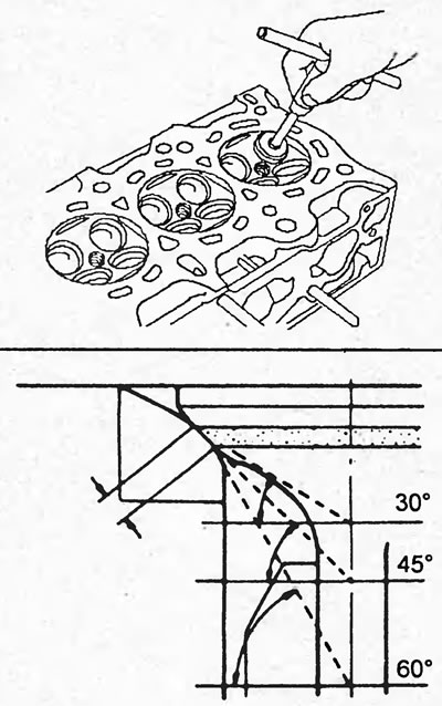
D15B, D17A.
b) (K20A) Using carbide cutters with the cone angles shown in the figure below, grind the valve seats, removing a minimum layer of metal only to clean the working chamfers of the seats.
Normal chamfer width is 1.25-1.55 mm
Maximum chamfer width: 2.00 mm
Models with rocker arm block types 1 and 2.
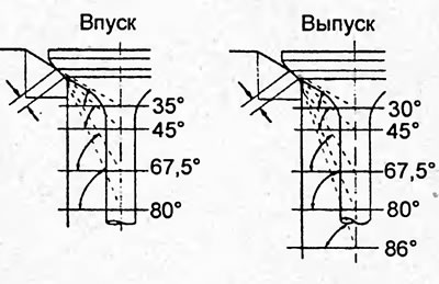
Models with type 3 rocker arm block.
c) Apply a thin layer of white paint to the valve face. Press the working face of the valve against the seat, but do not rotate the valve. Then remove the valve and inspect the seat and the valve face.
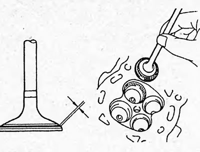
- If paint remains around the entire circumference (360°) of the valve bevel, the valve is concentric. Otherwise, replace the valve.
- If paint shows up all the way around (360°) the valve seat, the valve guide and valve seat are concentric. Otherwise, regrind the chamfer.
- Make sure the contact patch is in the middle of the valve face and is the correct width.
d) Otherwise, adjust the chamfer as follows:
D15B, D17A:
- If the contact patch is located too high on the valve chamfer, use cutters with a cone angle of 67.5° (inlet), 60° (outlet) and 45° to regrind the seat (see the figure in point "a").
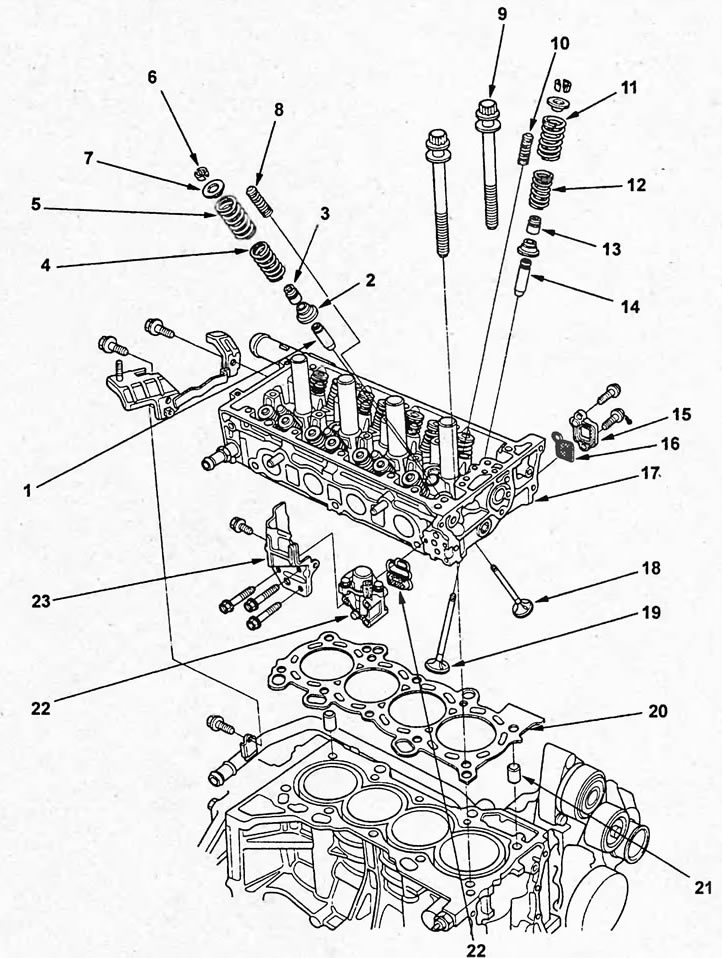
Disassembly and assembly of the cylinder head (K20A). 1,14 - guide sleeve, 2 - valve spring seat, 3, 13 - oil seal, 4, 12 - valve spring No.2, 5, 11 - valve spring No.1, 6 - crackers, 7 - valve spring plate, 8, 10 - plunger, 9 - cylinder head mounting bolts, 15 - variable valve timing system (VTC) valve filter housing, 16 - variable valve timing system (VTC) valve filter, 17 - cylinder head, 18 - exhaust valve, 19 - intake valve, 20 - cylinder head gasket, 21 - variable valve timing and valve lift system (VTEC) valve filter, 22 - variable valve timing and valve lift system (VTEC) valve, 23 - heat shield screen of the valve of the variable valve timing and lift height system of the valve
- If the contact patch is located too low on the valve chamfer, use cutters with a cone angle of 30° and 45° to regrind the seat (see the figure in point "a").
Note: Always perform the final sanding with a 45° cone cutter.
K20A:
- If the contact patch is located too high on the valve chamfer, use cutters with a cone angle of 67.5° and 45° to regrind the seat (see the figure in point "b").
- If the contact patch is located too low on the valve chamfer, use cutters with a cone angle of 35° (inlet), 30° (outlet) and 45° to regrind the seat (see the figure in point "b").
Note: Always perform the final sanding with a 45° cone cutter.
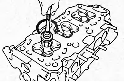
11. Manually lap the valve and valve seat using abrasive paste. After lapping, clean the valve and valve seat.
12. Check the height of the valve protrusion relative to the base of the spring seat - dimension "L".
Nominal size:
- D15B, D17A - 53.17 - 53.64 mm
K20A:
- inlet - 40.80 - 41.00 mm
- release - 54.60 - 54.80 mm
Maximum size:
- D15B, D17A — 53.89 mm
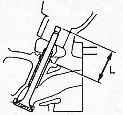
If the "L" dimension exceeds the permissible limit, replace the cylinder head.
13. Check the thread diameter of the cylinder head mounting bolts at locations (A) and (B) shown in the figure.
Minimum diameter - 10.6 mm
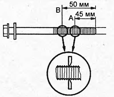
Replace the bolt if necessary.
14. Check the valve springs. Use a caliper to measure the length of the spring in its free state.
Spring length:
D15B - 58.7 mm
D15B (lean mixture):
- inlet - 57.92 mm
- release - 65.49 mm
D15B, D17A with VTEC system:
- inlet - 56.49 mm
- release - 58.70 mm
K20A:
inlet:
- spring #1 - 45.22 mm
- spring #2 - 50.86 mm
release:
- spring #1 - 45.50 mm
- spring #2 - 51.81 mm
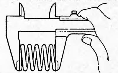
If the spring length differs from the nominal length, replace the valve spring.
15. Check the camshaft and bearings.
A. Check the camshaft for bending.
a) Place the camshaft on the prisms.
b) Using a dial indicator, check the runout of the camshaft relative to the center journal.
Nominal runout - 0.03 mm
Maximum runout - 0.04 mm
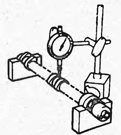
If the runout exceeds the permissible value, replace the camshaft.
B. Measure the camshaft lobe height.
Note (K20A): The engines of this vehicle are equipped with 3 types of VTEC rocker arm assemblies and each type of rocker arm assembly is equipped with a camshaft corresponding to the given type of rocker arm assembly.
Nominal height:
D15B models without VTEC system:
- intake - 35.299 mm
- release - 37.281 mm
D15B models with VTEC system:
inlet:
- primary - 38.427 mm
- secondary - 32.292 mm
release - 38,784 m
D17A:
inlet:
- primary - 38.604 mm
- secondary - 32.848 mm
release 38.784 mm
K20A:
Type 1:
inlet:
- primary - 33.925 mm
- secondary - 29.638 mm
release - 34.092 mm
Type 2:
inlet:
- primary - 29.218 mm
- average - 34.415 mm
- secondary - 33.076 mm
release - 34.092 mm
Type 3:
inlet:
- primary - 32.621 mm
- average - 35.534 mm
- secondary - 32.449 mm
release:
- primary - 32.437 mm
- average - 34.661 mm
- secondary - 32.269 mm
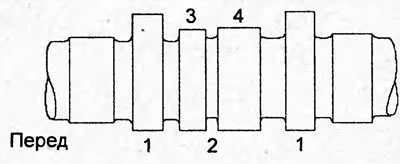
D15B, D17A models with VTEC system. 1 - exhaust, 2 - intake, 3 - primary cam, 4 - secondary cam.
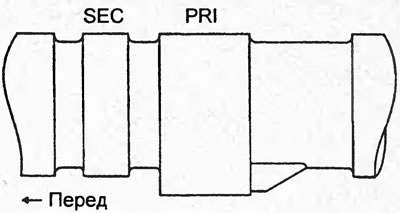
K20A (type 1). SEC - secondary cam, PRI - primary cam.
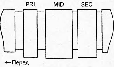
K20A (type 2). SEC - secondary cam, PRI - primary cam, MID - middle cam.
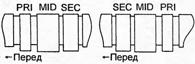
K20A (type 3). SEC - secondary cam, PRI - primary cam, MID - middle cam.
B. Check the radial oil clearance in the camshaft bearings.
a) Place a plastic feeler gauge on each camshaft bearing journal.
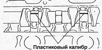
b) Install the camshaft bearing caps (see section "Cylinder head").
c) Remove the camshaft bearing caps (see section "Cylinder head").
d) After measuring the width of the gauge, determine the gap.
Nominal clearance:
D15B, D17A - 0.050 - 0.089 mm
K20A:
- neck No.1 - 0.030 - 0.069 mm
- the rest - 0.060 - 0.099 mm
Minimum gap - 0.15 mm
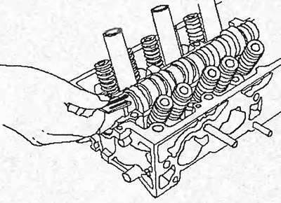
D15B, D17A.
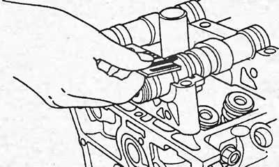
K20A.
D. Check the axial clearance of the camshaft. To do this, install the camshaft. Using a dial indicator, measure the axial clearance while moving the camshaft back and forth.
Nominal axial clearance:
- D15B, D17A — 0.05-0.15 mm
- K20A — 0.05 - 0.20 mm
Maximum axial clearance:
- D15B, D17A — 0.5 mm
- K20A 0.4 — mm
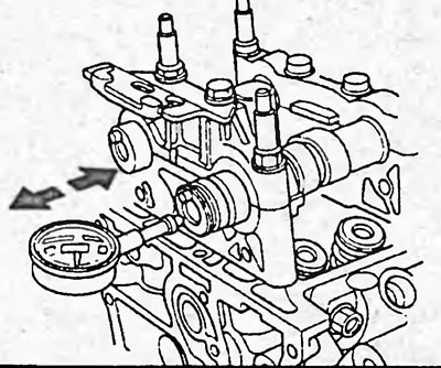
If the axial clearance is greater than maximum, replace the camshaft and cylinder head.
12. Check the oil clearance between the rocker arm and the rocker arm shaft.
a) Measure the inner diameter of the rocker arm.
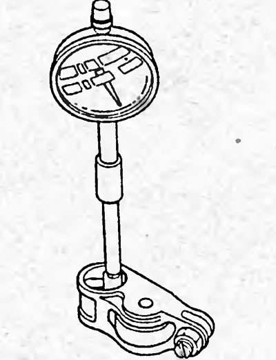
b) Measure the outside diameter of the rocker arm shaft.
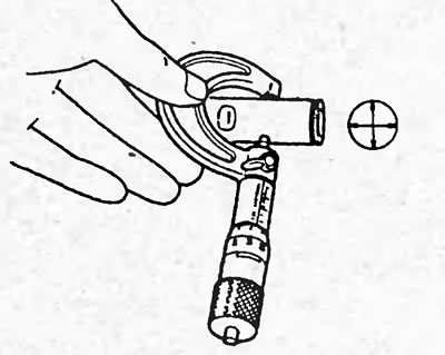
c) Calculate the oil clearance.
Oil clearance:
D15B, D17A:
Nominal:
- inlet - 0.017 - 0.050 mm
- release - 0.018 - 0.054 mm
Maximum 0.08 mm
R20A:
Nominal:
- inlet - 0.025 - 0.052 mm
- release - 0.018 - 0.056 mm
Maximum - 0.08 mm
Replace rocker arms and/or rocker shaft if necessary.
14. Check the rocker arm timing pins (A). Insert the pin into the main rocker arm hole (B) and make sure it moves smoothly.
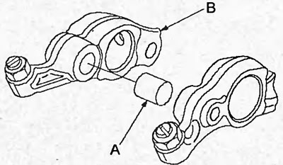
D15B, D17A.
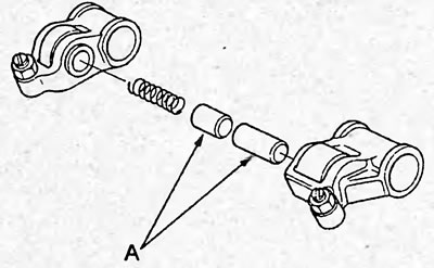
K20A (for the rocker block of the UTES system type 1).
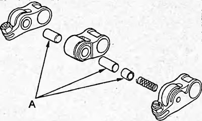
K20A (for VTEC rocker arm blocks types 2 and 3).
Replace the rocker arm if necessary.
Assembly
1. Apply a layer of oil to the valve stems and install the valves into the guide bushings. Check that the valves move smoothly.
2. Install the spring seats onto the cylinder head.
3. Install the oil seals using a special tool.
Note: The exhaust valve stem seal (C) has a black spring (D), and the intake valve stem seal (E) has a white spring (F). Do not confuse them.
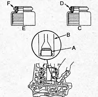
4. Install the valve springs and install the crackers by compressing the valve springs with a special tool.
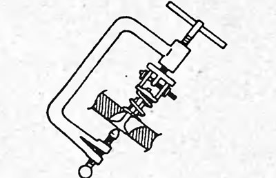
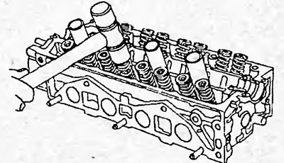
5. Tap the valves lightly with a plastic-faced hammer to ensure that the valves and keepers are in the correct position. Tap only along the valve axis.
6. Install the VTEC rocker arm assembly.
7. Install the camshafts.
(Article source on the website Hondabook.ru)