
Contents: Removal ⇊ Disassembly, inspection and assembly…⇊ Installation ⇊ Replacing crankshaft seals ⇊
Removal
Note:
- Relieve any residual fuel pressure before removing the fuel supply hose.
- The fluid in the cooling system is under pressure. Make sure the engine is cool before removing the radiator cap to avoid steam burns.
- The garage jack and hoist hooks must be securely installed in specially designated places.
- Disconnect connectors and remove hoses carefully and do not mix them up when installing.
1. Secure the hood in the fully open position.
2. Before carrying out any work, turn off the vehicle's security system.
3. Disconnect the wires from the positive (+) and negative (-) terminals of the battery.
Note: Disconnect the wire from the negative terminal first, then from the positive terminal.
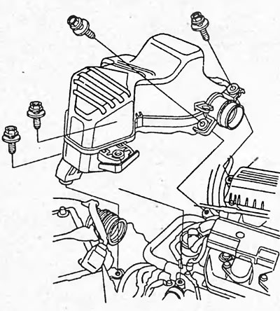
4. Remove the intake resonator.
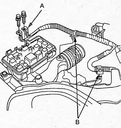
5. Disconnect the power wires (A) from the fuse box, disconnect the wire clamps (B).
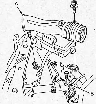
6. Remove the air intake duct (A) and ground wire (B).
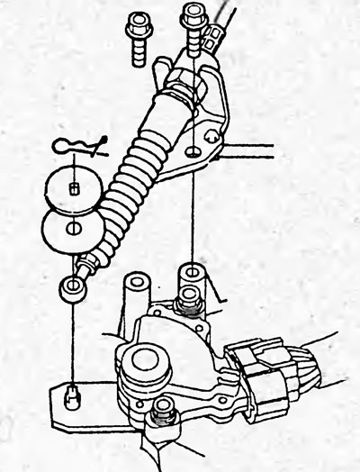
7. (CVT) Remove the control cable.
Caution: Do not bend the cable. If the cable is bent, it must be replaced.
8. Reduce residual pressure in the fuel system.
9. Disconnect the fuel vapor canister hose (A) and the brake booster hose (B).
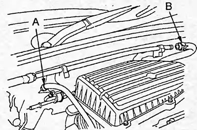
Sedan models.
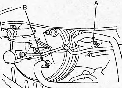
Hatchback models.
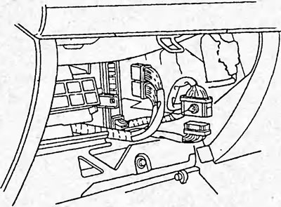
10. Remove the fasteners and then open the glove compartment.
11. Disconnect the connectors from the powertrain control unit and the engine control unit.
12. Disconnect the wire harness clamps (A) and seal (B) and pull the wire harness through the access hole.
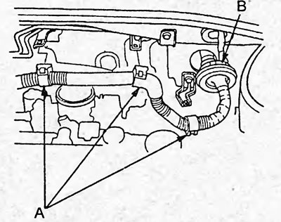
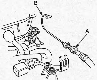
13. Remove the throttle cable (B) by loosening the lock nut (A) and pull it out of the brackets.
Caution: Do not bend the cable. If the cable is bent, it must be replaced.
14. Remove the generator.
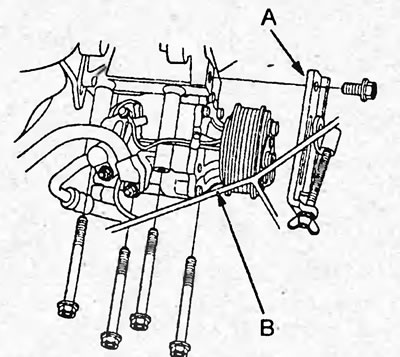
15. Remove the lower bracket (A) of the generator, then remove the air conditioning compressor (B) without disconnecting the hoses.
16. Remove the radiator cap.
17. Raise the car on a lift.
18. Remove the front wheels.
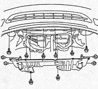
19. Remove the lower protection.
20. Drain the coolant, transmission fluid, and engine oil.
21. (Models with catalytic converter) Disconnect the oxygen sensor connectors (A) and remove the exhaust pipe (B).
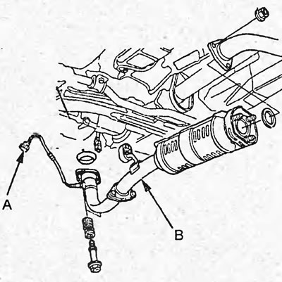
22. (Models without catalytic converter) Remove the exhaust pipe.
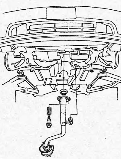
23. (Models with automatic transmission) Remove the protective covers (A), then remove the automatic transmission control cable (B).
Caution: Do not bend the cable. If the cable is bent, it must be replaced.
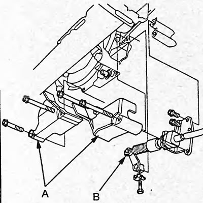
24. Disconnect the ball joint of the lower arm of the front suspension and the stabilizer bar.
25. Remove the propeller shafts.
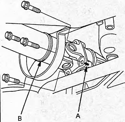
Note: Lubricate all contact surfaces with clean engine oil. After removal, wrap the ends of the propeller shafts with a cloth to protect them. 26. (4WD) When removing the propeller shaft (B), apply a timing mark (A) to the flange of the transfer case and propeller shaft as shown in the figure.
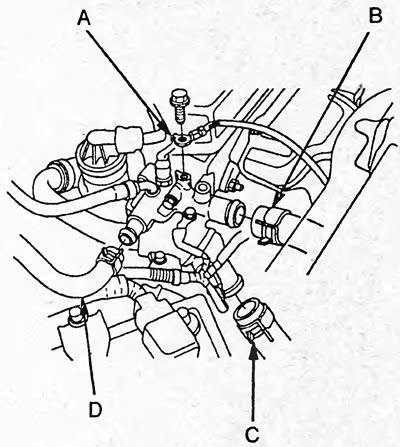
27. Disconnect the ground wire (A), upper (B) and lower (C) radiator hoses and the interior heater hose (D).
28. Remove the interior heater hose.
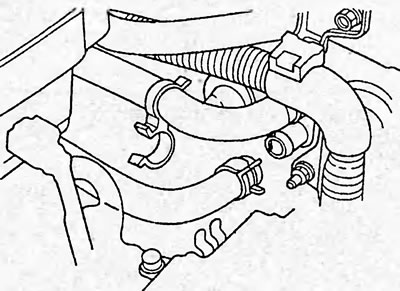
29. Disconnect the automatic transmission fluid cooler hoses and install plugs in the hoses.
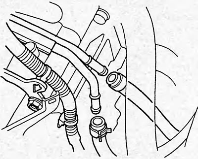
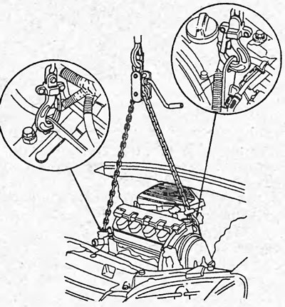
30. Attach the engine lifting tool to the brackets.
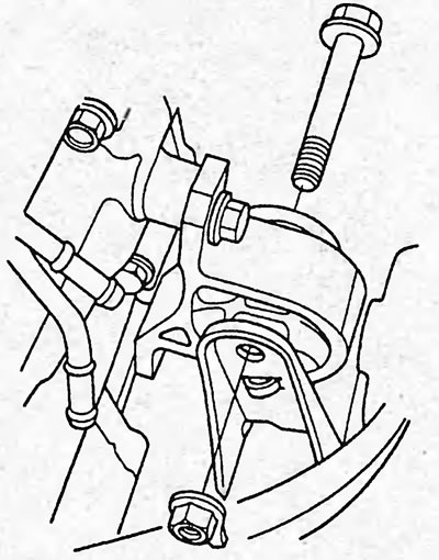
31. Loosen the front engine mount mounting bolt.
32. Unscrew the nuts securing the side engine support.
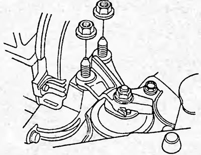
33. Unscrew the gearbox mounting bolts and nuts.
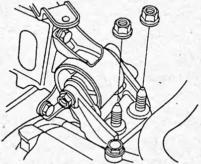
Models with automatic transmission.
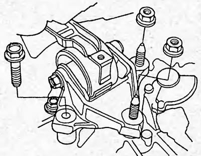
Continuously variable transmission (CVT).
34. Raise the engine slightly and remove the rear engine mount mounting bolt.
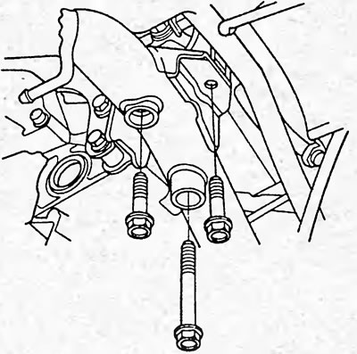
2WD models.
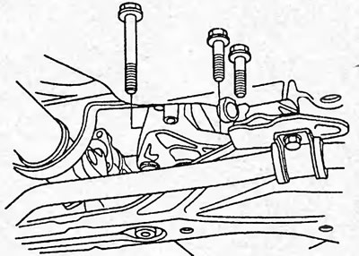
4WD models.
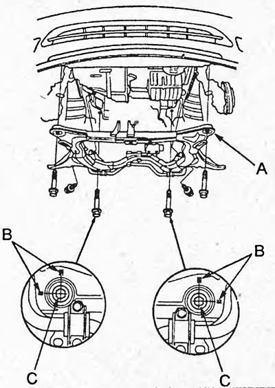
35. Apply alignment marks (B) for subsequent alignment with the rear subframe mounting bolts (C) and remove the rear subframe (A) by unscrewing the mounting bolts.
36. Make sure all wires, hoses and connectors are disconnected from the engine.
37. Carefully remove the engine from the engine compartment.
Disassembly, inspection and assembly of the cylinder block
The procedures for disassembling, checking and assembling the cylinder block are discussed in the chapter "Engine - General Repair Procedures".
Installation
1. Install the brackets, stiffeners and tighten the mounting bolts as shown in the figure "Installing the brackets and stiffeners".
2. Install the engine into the engine compartment.
Caution: Install parts only in the sequence shown below, installation in a different sequence may result in noise and vibration during engine operation.
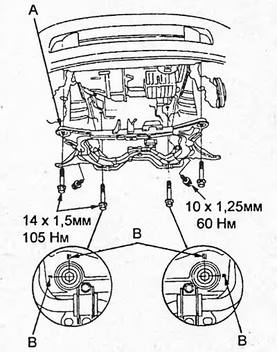
3. Install the rear subframe (A), aligning the marks (B) on it with the heads of the mounting bolts, and tighten the mounting bolts.
4. Tighten the rear engine mount mounting bolts.
Tightening torque - 59 Nm
5. Tighten the side engine support mounting nuts.
Tightening torque - 54 Nm
6. Tighten the gearbox support mounting nuts.
Tightening torque - 54 Nm
7. Tighten the front engine mount mounting bolts.
Tightening torque - 64 Nm
8. Disconnect the special engine lifting device.
9. Install the cardan shafts.
10. Connect the ball joint of the lower arm of the front suspension and the stabilizer bar.
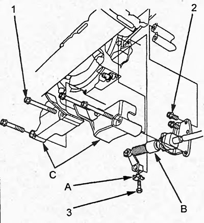
11. (Models with automatic transmission) Install the protective covers (A) and install the automatic transmission control cable (B).
Tightening torque:
- bolts "1" and "2" - 10 Nm
- bolts "3" - 14 Nm
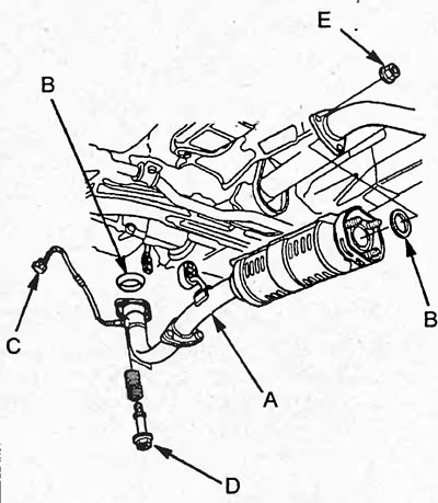
12. (Models with catalytic converter) Install the exhaust manifold (A), new gasket (B) and tighten the new mounting nut (C). Connect the connectors to the oxygen sensor (D).
Tightening torque:
- nut "E" - 33 Nm
- nut "D" - 22 Nm
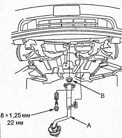
13. (Models without catalytic converter) Install the exhaust pipe (A) with a new gasket (B).
14. Install the front protection.
15. Install the front wheels.
16. Connect the automatic transmission fluid cooler hoses and install a plug in the hose.
17. Connect the interior heater hose.
18. Install the upper, lower radiator hoses, interior heater hose and ground wire.
Tightening torque - 10 Nm
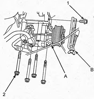
19. Install the air conditioning compressor, then install the lower generator bracket and tighten the mounting bolts.
Tightening torque:
- bolts "2" - 24 Nm
- bolt "1" - 44 Nm
20. Pull the wire harness through the access hole and install the seal and wire harness clamps.
21. Connect the connectors to the control unit and the main connector.
22. Install the fasteners and close the glove compartment.
23. Install and adjust the throttle cable.
24. Connect the brake booster, fuel vapor collector and fuel supply hoses.
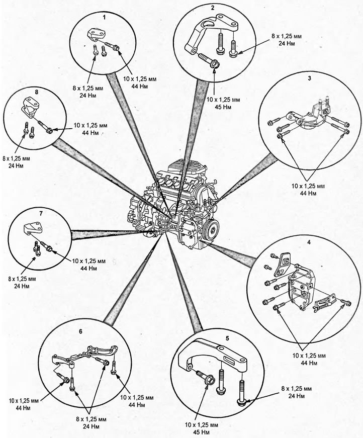
Installation of brackets and stiffeners. 1 - rear stiffener (D15B, D17A 2WD models with automatic transmission and VTEC system), 2 - rear stiffener (4WD models), 3 - engine support bracket, 4 - air conditioning compressor bracket, 5 - front stiffener (D15B 4WD models), 6 - stiffening rib (D15B 2WD models), 7 - front stiffener (D15B, D17A models with VTEC system), 8 - rear stiffener (D15B, D17A models with VTEC system with continuously variable transmission (CVT)).
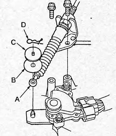
25. (CVT) Install the control cable (A) with a new plastic washer (B), washer (C) and spring clip (D).
Tightening torque - 26 Nm
26. Install the battery bracket.
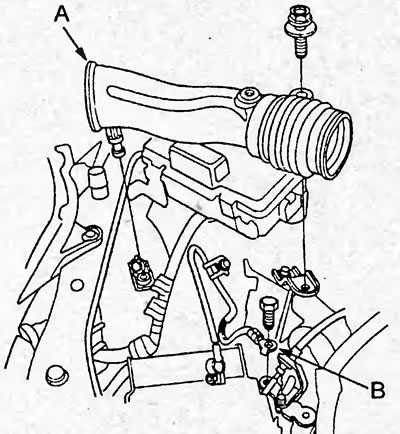
27. Install the air intake duct (A) and ground wire (B).
Tightening torque - 10 Nm
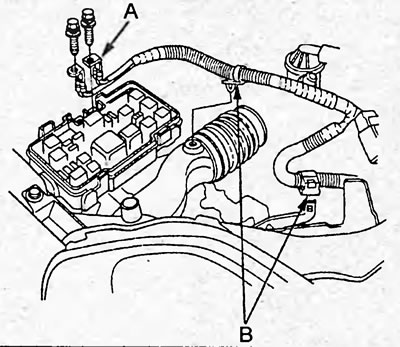
28. Connect the power wires (A) to the fuse box and the wire clamps (B).
29. Install the intake resonator.
Tightening torque - 12 Nm
30. Fill with coolant, engine oil, and transmission fluid.
31. Start the engine and check for leaks.
Replacing crankshaft seals
1. Replace the front crankshaft oil seal.
a) Using a screwdriver and hammer, knock the oil seal out of the oil pump.
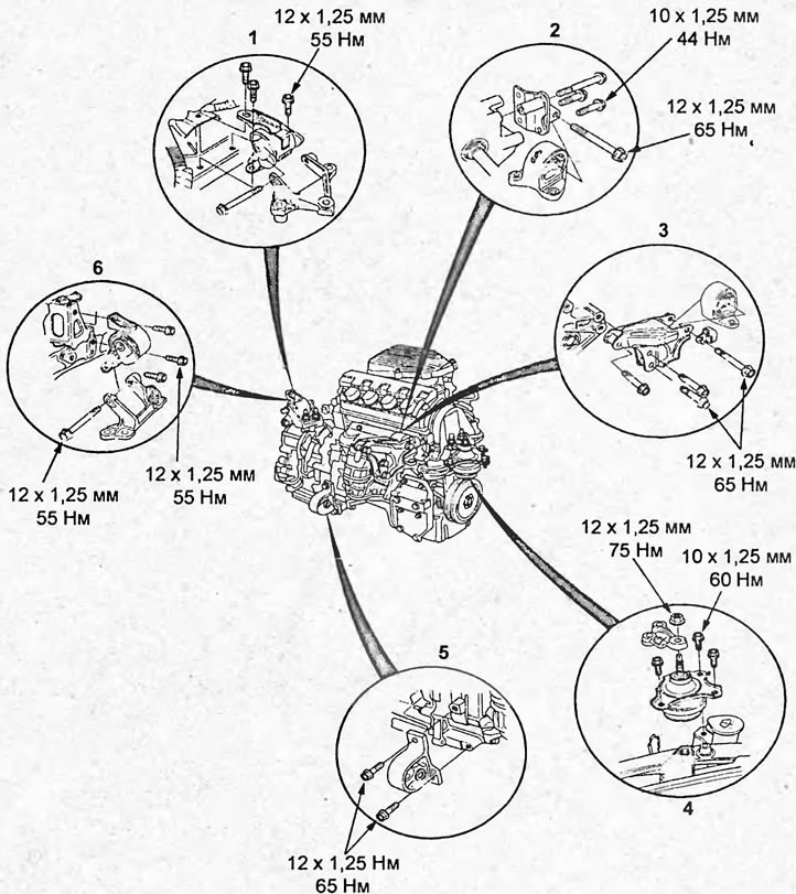
Installation of power unit supports. 1 - gearbox mounting bracket (variator (CVT)), 2 - rear support (4WD models), 3 - rear support (2WD models), 4 - side engine mount, 5 - front engine mount, 6 - gearbox mounting bracket (models with automatic transmission).
b) Using a drift or tube of suitable diameter and a hammer, press in the new oil seal until its surface is flush with the oil pump.
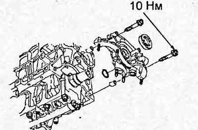
c) Apply grease to the lip of the oil seal.
2. Replace the rear crankshaft oil seal.
a) Using a screwdriver and hammer, knock out the seal.
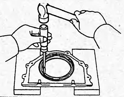
b) Using a mandrel or pipe of suitable diameter and a hammer, press in the new seal.
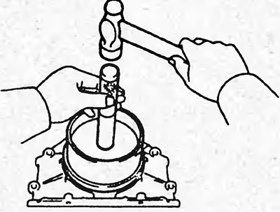
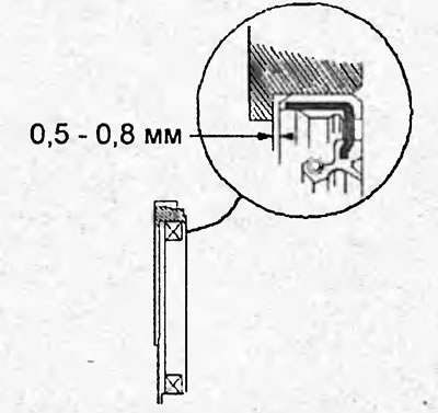
c) Make sure there is a gap between the oil seal and the rear surface of the rear oil seal holder.
Gap - 0.5 - 0.8 mm
(Based on materials from the website: «HondaBook.ru»)