
Removal
Note: After removing the timing belt, check the coolant pump.
1. Before carrying out any work, turn off the vehicle's security system.
2. Disconnect the cable from the positive and negative terminals of the battery.
Note: Disconnect the wire from the negative terminal first, then from the positive terminal.
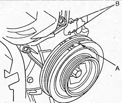
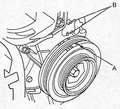
3. Turn the crankshaft pulley and set it so that the TDC mark (A) on the pulley is aligned with the reference mark (B), as shown in the figure.
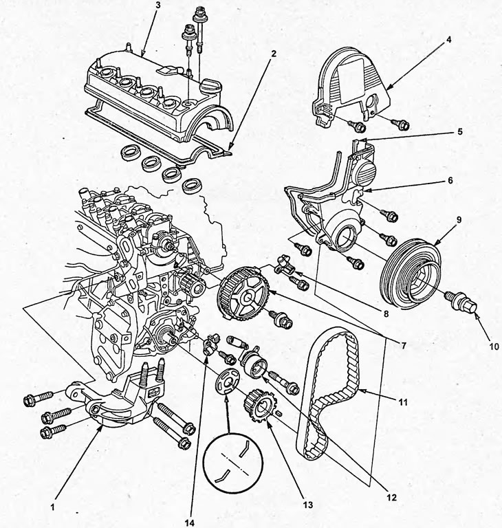
Removal and installation the timing belt. 1 - front engine mount, 2 - cylinder head cover gasket, 3 - cylinder head cover, 4 - upper timing belt cover, 5 - rubber gasket, 6 - lower timing belt cover, 7 - camshaft toothed pulley, 8 - camshaft position sensor, 9 - crankshaft pulley, 10 - crankshaft pulley mounting bolt, 11 - timing belt, 12 - timing belt tensioner, 13 - timing belt drive pulley, 14 - crankshaft position sensor.
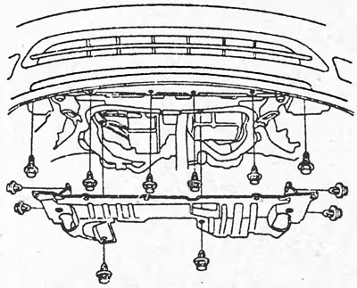
4. Remove the front wheels and lower protection.
5. Remove the generator.
6. Remove the cylinder head cover (see section "Checking and adjusting thermal clearances in the valve drive").
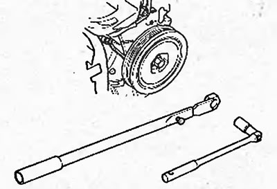
7. Holding the crankshaft pulley from turning with a special tool, unscrew the pulley mounting bolt.
8. Jack up the engine. Place a wooden block between the jack foot and the engine.
Note: Do not place the jack in the center of the oil pan to avoid damaging the pan.
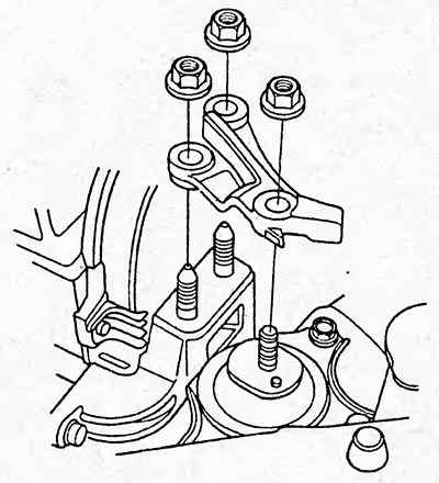
9. Remove the upper engine mount bracket.
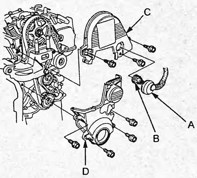
10. Remove the seal (A) and disconnect the camshaft position sensor connector (B) from the upper timing belt cover. Remove the upper (C) and lower (D) timing belt covers.
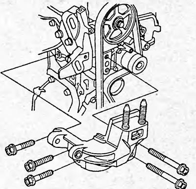
11. Remove the front engine mount.
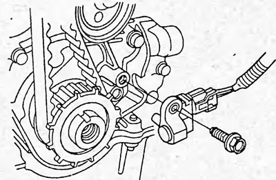
12. Remove the crankshaft position sensor from the oil pump without disconnecting the connector.
13. Apply a force of 98 N to the middle of the timing belt between the camshaft pulley and the coolant pump pulley and make sure that the belt tensioner moves smoothly. Replace the tensioner if necessary.
14. Loosen the timing belt tension by turning the tensioner counterclockwise and remove the belt.
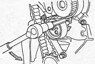
15. If necessary, remove the timing belt tensioner by unscrewing the mounting bolt.
Examination
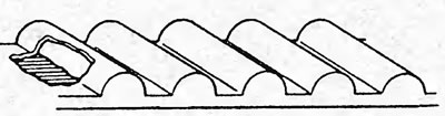
1. Check the timing belt and timing belt covers for the following defects:
- a) Check that the timing belt is installed correctly.
- b) Check the timing belt cover gaskets for damage and correct installation.
- c) If the belt teeth are damaged or cracked, check that the camshaft and coolant pump are not seized.
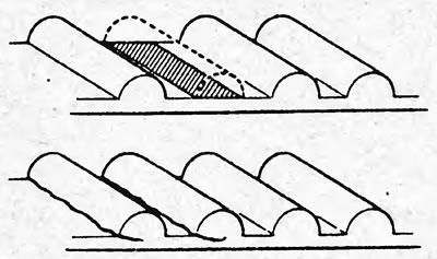
- d) If significant wear is observed on the non-running side of the belt, check for nicks on the tension roller side.
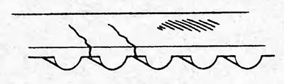
- d) If wear or damage is found on only one side of the belt, check the belt guide and the correct positioning of the pulleys.
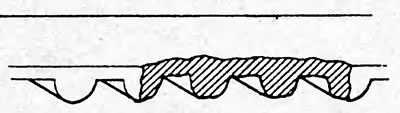
- e) If there is significant wear on the belt teeth, check the timing belt cover for damage. If necessary, replace the timing belt.
2. Check the timing belt tensioner.
a) Place the tensioner on a flat, horizontal surface.
b) Measure the distances from the base of the tensioner to points "A" and "B" as shown in the figure.
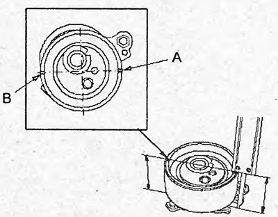
c) Subtract one distance from the other and check the difference.
The difference is no more than 0.75 mm
Replace the tensioner if necessary.
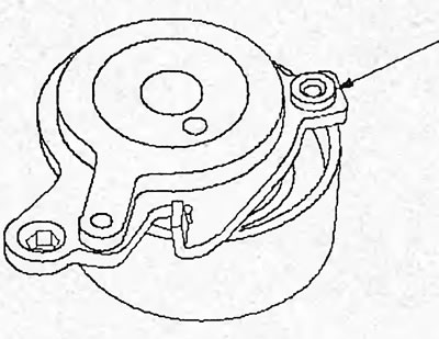
d) Check the tensioner spring seal. Replace if necessary.
Installation
Note: Before installation, wipe the timing belt pulleys and covers with a rag.
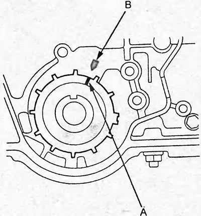
1. Set the timing belt drive pulley to TDC. Align the mark (A) on the pulley with the pointer (B) on the oil pump.
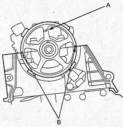
2. Set the camshaft pulley to TDC. The "UP" mark (A) on the pulley should be facing upwards, and the marks (B) should lie in the plane of the cylinder head.
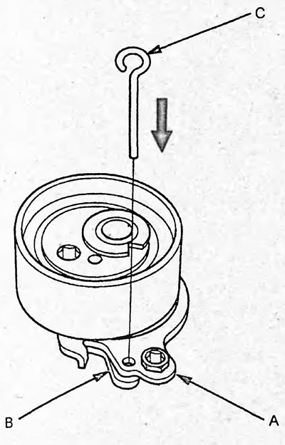
3. Install the timing belt tensioner if removed.
a) Align the holes in the tensioner roller base (A) and the tensioner base (B) and insert the ∅ 3 mm pin (C) into the aligned holes.
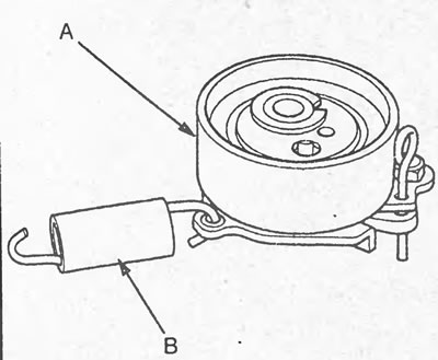
b) Install the tensioner spring (B) onto the tensioner (A).
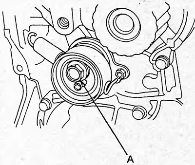
c) Install the timing belt tensioner and tighten the mounting bolt (A).
Tightening torque - 10 Nm
4. Loosen the tensioner mounting bolt by turning it 180°.
5. Install the timing belt onto the pulleys in the sequence shown in the figure.
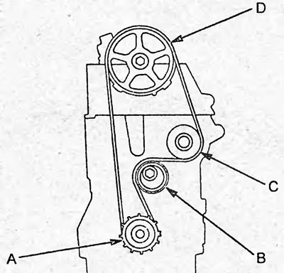
A - timing belt drive pulley, B - tensioner roller, C - coolant pump drive pulley, D - camshaft pulley.
6. Install the tensioner spring onto the tension bolt.
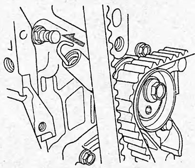
7. Turn the timing belt drive pulley 2 turns counterclockwise to position the belt.
8. Set the piston of cylinder No.1 to the TDC position.
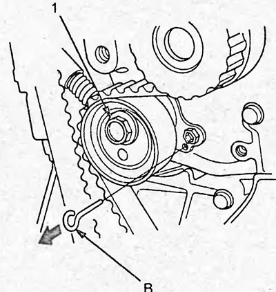
9. Tighten the tensioner mounting bolt (1) to the torque specified below and remove the pin (B) from the tensioner hole.
Tightening torque - 44 Nm
10. Install the crankshaft position sensor and tighten the mounting bolt.
Tightening torque - 12 Nm
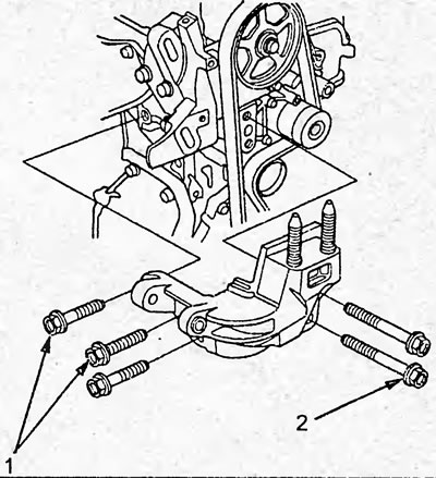
11. Install the front engine mount and tighten the mounting bolts in the sequence shown in the figure.
Tightening torque - 44 Nm
12. Install the lower timing belt cover and tighten the mounting bolts.
Tightening torque - 10 Nm
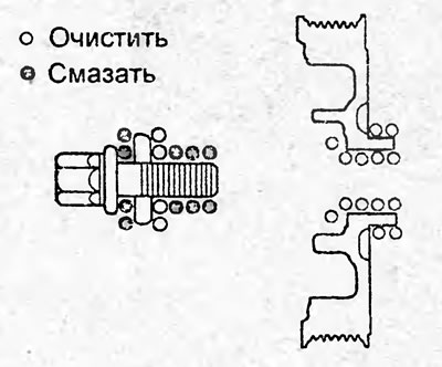
13. Clean the crankshaft pulley and pulley mounting bolt. Apply a coat of grease to the mounting bolt as shown in the figure.
14. Install the crankshaft pulley and, holding it with a special tool, tighten the mounting bolt.
Tightening torque:
- stage 1 - 20 Nm
- stage 2 - 90°
15. Turn the crankshaft pulley 5-6 turns counterclockwise to bring the timing belt into the desired position.
16. Turn the crankshaft pulley and install it so that the TDC mark (A) on the pulley is aligned with the reference marks (B), as shown in the figure.
17. Check the position of the marks on the camshaft pulley.
a) If the marks are in the position indicated in point "3", then proceed further.
b) If the marks are not in the position specified in point "3", then remove the timing belt and repeat the installation procedure (points 2-15).
18. Install the upper timing belt cover and tighten the mounting bolts. Connect the camshaft position sensor connector and install the rubber seal.
Tightening torque - 10 Nm
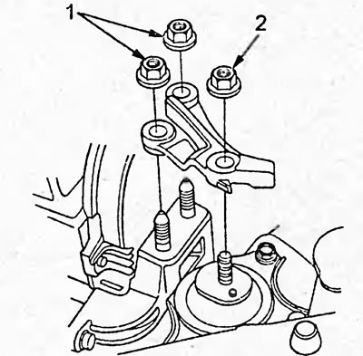
19. Install the upper engine mount and tighten the nuts in the sequence shown in the figure.
Tightening torque - 54 Nm
20. Install the cylinder head cover (see section "Checking and adjusting thermal clearances in the valve drive").
21. Install the generator, generator drive belt and adjust the belt tension.
22. Install the lower protection and wheels.
23. Connect the wire to the negative terminal of the battery.
[The original can be found on the resource: HondaBook]