
Reading fault codes
Using a scanner
1. Connect the scanner (A) to the diagnostic connector (B).
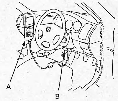
2. Turn the ignition key to the "ON" position and read the fault codes.
Note: For more details on the code reading procedure, see the scanner instructions.
3. After reading the codes and troubleshooting, erase the codes (see the subsection "Erasing trouble codes").
Without using a scanner
1. With the ignition off, connect the special tool to the diagnostic connector.
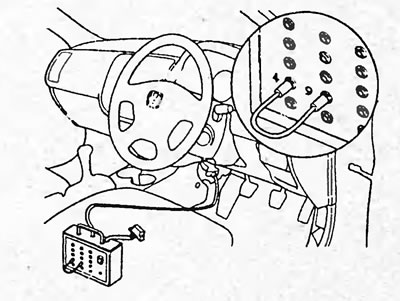
2. Using a jumper, short-circuit the terminals "4" and "9" of the special device. Turn on the switch of the special device.
3. Turn the ignition key to the "ON" position.
4. Read the fault codes by the number of flashes of the EPS indicator (see the figure "Reading fault codes").
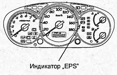
Hatchback.
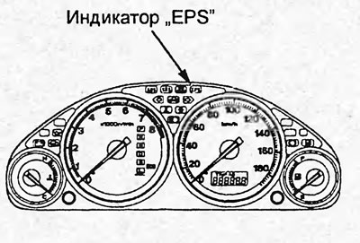
Sedan.
Notes:
- The fault codes are repeated until the ignition key is turned to the "OFF" position.
- If there is a malfunction, after a pause of 3 seconds, the codes are displayed.
- The output of codes starts from the smallest.
- The first sequence of flashes corresponds to the first digit of the diagnostic code, which consists of two digits. After a pause of 2 seconds, the second sequence of flashes is displayed, corresponding to the second digit of the code.
5. After reading the fault codes, turn the ignition key to the "OFF" position and disconnect the special tool from the diagnostic connector.
6. After troubleshooting, erase the codes (see the subsection "Erasing trouble codes").
Erasing codes
Note: Codes stored in the EEPROM memory cannot be erased by disconnecting the battery.
Using a scanner
1. Connect the scanner (A) to the diagnostic connector (B).
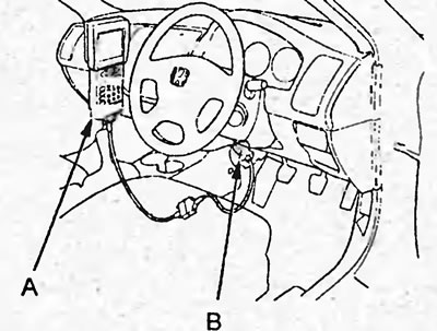
2. Turn the ignition key to the "ON" position and erase the fault codes.
Note: For more details on the code erasing procedure, see the scanner instructions.
Without using a scanner
1. Make sure the steering wheel position is correct for straight ahead driving.
2. With the ignition off, connect the special tool to the diagnostic connector.
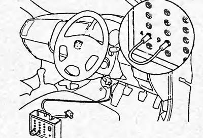
3. Using a jumper, close the terminals "4" and "9" of the special device. Turn on the special device.
4. Turn the steering wheel to the left by 45° relative to the straight-ahead position.
5. Turn the ignition key to the "ON" position (the EPS indicator should come on for 4 seconds and go out).
6. After the indicator goes out, turn the steering wheel to the straight ahead position (after 4 seconds the indicator will light up for 4 seconds and then go out).
7. When the indicator lights up, turn the steering wheel 45° to the left again.
8. After the indicator goes out, return the wheel to the straight ahead position and check that after 4 seconds the indicator lights up and goes out twice.
Note: If the indicator does not light up twice, the code erasure procedure has failed. In this case, turn off the ignition ("OFF") and repeat the procedure.
10. Turn off the ignition. Remove the jumper or disconnect the special tool.
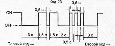
Reading fault codes.
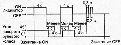
Clearing fault codes.
Table: EPS system diagnostic trouble codes.
| Code | Malfunction | Possible location of the malfunction |
| 12 | Torque sensor - fault in T/S IG circuit | Torque sensor; Wiring; Connecting connectors. |
| 16 | Main and additional torque sensors - malfunction | Torque sensor; Wiring; Connecting connectors. |
| 17 | Torque sensor - incorrect supply voltage (12V) | Torque sensor; Wiring; Connecting connectors. |
| 18 | Torque sensor - incorrect supply voltage (5V) | Torque sensor; Wiring; Connecting connectors. |
| 22 | Inconsistency between the speed sensor and the crankshaft position sensor | Vehicle speed sensor; Crankshaft Position Sensor; Wiring; EPS control unit; Engine and automatic transmission control unit. |
| 23 | Engine Crankshaft Speed Sensor - Circuit Malfunction | Crankshaft Position Sensor; Wiring; EPS control unit; Engine and automatic transmission control unit. |
| 37 | Electric motor - circuit failure | Electric motor; EPS control unit; Wiring. |
| 41 | Electric motor - circuit failure | Electric motor; EPS control unit; Wiring. |
| 42 | Electric motor supply voltage | Electric motor; EPS control unit; Wiring. |
| 43 | Electric motor supply voltage | |
| 45 | Feedback signal does not match the set value | |
| 47 | Malfunction in the motor relay circuit | EPS control unit; Wiring. |
| 50 | EPS control unit processor | EPS control unit |
| 51 | EEPROM memory | EPS control unit |
| 62 | "Fail Safe" relay - stuck in "ON" position | EPS control unit |
| 64 | Low supply voltage; Bad contact of the "File Safe" relay. | Battery, Fuse #18 (60 A) in the fuse box in the engine compartment; EPS control unit. |
| 66 | Malfunction in the power supply circuit | Wiring |
| 67 | Torque sensor - fault in "I/F" circuit | Torque sensor; Wiring; Connecting connectors. |
| 68 | EPS control unit internal circuit malfunction | EPS control unit |
| 69 |