
Contents: Examination ⇊ Removal and installation ⇊
Examination
Check the voltage at the terminals of the EPS control unit and compare the measured values with those given in the table "Checking the signals at the terminals of the EPS control unit".
Replace the faulty element if necessary.
Table. Checking signals at the EPS control unit terminals.

| Conclusion | Output name | Wire colors | Examination | |||||
| Compound | Verification conditions | Result | ||||||
| A1 | +B | W/BI | A1 <-> GND | Constantly | VB | |||
| A2 | PG | IN | A2<-> GND | - | - | |||
| B1 | M1 | R | B1 <-> GND | The engine is running, the steering wheel is turning | 0<->7-14V | |||
| B2 | M2 | G | B2 <-> GND | The engine is running, the steering wheel is turning | 7-14<->0B | |||
| C1*1 | VT6 | Y/R | C1 <-> GND | The engine is running, the steering wheel is turning | 0 <-> 5 V | |||
| C2 | T/S GND | R | C2 <-> GND | - | - | |||
| SZ | VCC1 | ABOUT | SZ GND | The engine is started | Vv | |||
| Ignition is off | 0B | |||||||
| C5*2 | VT6 | Y/R | C5 <-> GND | The engine is running, the steering wheel is turning | 0<->5B | |||
| C6 | WLP | Y/BI | C6 <-> GND | EPS indicator is not on | Vv | |||
| EPS indicator is on | 0B | |||||||
| C7 | VSP | BI/W | C7 <-> GND | The front wheels are spinning | Varies within 0 <-> 5 V | |||
Table. Checking signals at the terminals of the EPB control unit.(continuation)

| Conclusion | Output name | Wire colors | Examination | ||
| Compound | Verification conditions | Result | |||
| C8 | SCS | Br | C8 <-> GND | The "SCS" pin is shorted | 0 B |
| The "SCS" pin is not shorted | ≈5 V | ||||
| C10 | IG1 | Y | C10<->GND | The key in the ignition switch is in the "ON" (II) position | VB |
| The key in the ignition switch is in the "OFF" position | 0 B | ||||
| C11 | VCC2 | G/Y | C11<->GND | The engine is started | 5 V |
| Ignition is off | 0 B | ||||
| C13 | VT3 | BI/O | C13<->GND | The engine is running, the steering wheel is turning | 0 <-> 5 V |
| C15 | T/SIG | Y/B | C15<->GND | The engine is started | 0 <-> 5 V |
| C17 | PSW | Lg/B | C17<->GND | The engine is running, the steering wheel is turning | 0<->VB |
| C19 | NEP | Bl | C19<->GND | The engine is running at idle speed | 0<-> VB |
| C20 | DIAG-H | Gr | - | - | - |
Note:
- *1 - 50A;
- *2 - 60A.
Removal and installation
1. Disconnect the cable from the negative terminal of the battery.
2. Remove the lower trim panel on the passenger side (see chapter "Body").
3. Bend back the floor covering, unscrew the nuts and remove the control unit.
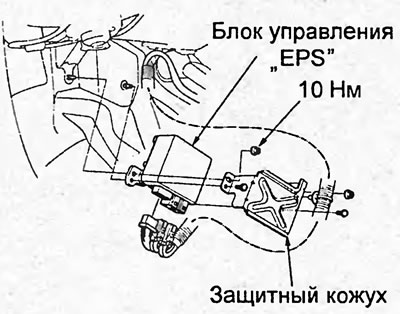
4. Disconnect the connector from the control unit.
Note:
- Installation is carried out in the reverse order of removal.
- After installation, start the engine and set the idle speed, turn the steering wheel from lock to lock several times and make sure the "EPS" indicator is off.
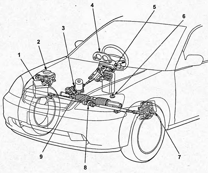
Component arrangement. 1 - battery, 2 - mounting block in the engine compartment, 3 - torque sensor, 4 - instrument cluster (ePS indicator), 5 - mounting block in the passenger compartment, 6 - diagnostic connector "DLC", 7 - EPS control unit, 8 - steering gear assembly, 9 - power steering motor.
(You will find the original on the portal: hondabook.ru)