
Contents: Reading fault codes ⇊ Reading fault codes using a…⇊ Reading fault codes from the "SRS"…⇊ Examples of error code output ⇊ Clearing fault codes ⇊ Table. Passive safety system fault…⇊ Table. Passive safety system fault…⇊ Table. Passive safety system fault…⇊ Authorization of the front passenger…⇊ Checking the current fault ⇊
Reading fault codes
1. Turn the ignition switch to the "ON" position, make sure the "SRS" indicator lights up.
If there are no fault codes, the indicator will go out after 6 seconds.
If the indicator remains on, read the fault codes.
Reading fault codes using a diagnostic tool
Connect the diagnostic tool to the connector (DLC). For detailed information on reading and clearing trouble codes, refer to the diagnostic tool operating instructions.
The fault codes are listed in the table "Fault codes for the passive safety system".
Note: If the diagnostic tool fails to read the trouble codes or displays "9-1" or "9-2", read the trouble codes from the "SRS" indicator.
Reading fault codes from the "SRS" indicator (models without service connector)
1. Turn the ignition switch to the "OFF" position and wait 10 seconds.
2. Connect the special tool (B) to the diagnostic connector (DLC) (A). Short-circuit (C) terminals "4" and "9" on the special tool and turn it on.
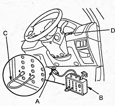
3. Turn the ignition switch to the "ON" position. Make sure that the "SRS" indicator comes on for 6 seconds.
4. Read the fault codes from the "SRS" indicator (D). The fault codes are listed in the "SRS fault codes" table.
5. Turn the ignition switch to the "OFF" position, wait 10 seconds and disconnect the special tool from the data link connector (DLC).
Examples of error code output
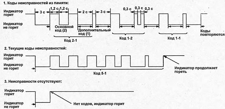
The fault code consists of two parts - the main code and the additional code. The main code is determined by long flashes (1.2 s), and the additional code by short ones (0.3 s). See the figure "Examples of fault code output".
Note:
- The fault codes are output from the memory in threes, in the reverse order of their recording in the passive safety system control unit, starting with the last code recorded. After the third code is output, the codes are repeated.
- The current fault code is displayed once, after the code is displayed the indicator will continue to light.
- If there are fault codes in memory and current fault codes, the codes are output as fault codes from memory.
- If there are no fault codes, the indicator will go out, come on and continue to burn.
- If the indicator remains on for a long time and no codes are output, check the indicator circuit.
- If the indicator does not light, check the indicator and wiring for an open or short circuit.
Clearing fault codes
1. Turn the ignition switch to the "OFF" position.
Examples of error code output
2. Connect the special tool (B) to the code erasing connector (A).
Caution: Do not use a jumper.
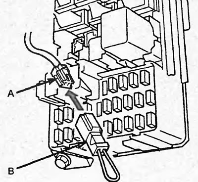
3. Turn the ignition switch to the "ON" position.
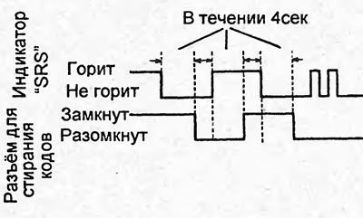
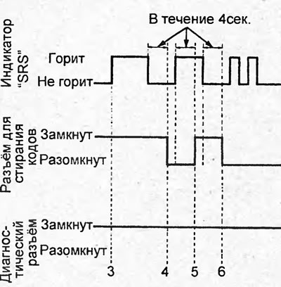
4. Make sure the "SRS" indicator comes on for 6 seconds and goes out. Disconnect the special tool from the code erasing connector within 4 seconds after the indicator goes out.
5. Make sure the "SRS" indicator lights up. Connect the special tool to the connector within 4 seconds after the indicator lights up.
6. Make sure the "SRS" indicator goes out. Disconnect the special tool from the code erasing connector within 4 seconds after the indicator goes out.
7. Check that the "SRS" indicator flashes twice.
8. Turn the ignition switch to the "OFF" position and wait 10 seconds. Turn the ignition switch to the "ON" position. If the passive restraint system is working properly, the "SRS" indicator will light for 6 seconds and go out.
Table. Passive safety system fault codes (sIEMENS and KEIHIN passive safety system control units) (sedan).
| Code | Possible location and cause of the malfunction | |
| 1-1 | Driver airbag circuit fault | Open or high resistance in the igniter circuit |
| 1-3 | Short circuit or low resistance in the igniter circuit | |
| 1-4 | Short circuit to power supply | |
| 1-5 | Short to ground | |
| 2-1 | Malfunction in front passenger airbag circuit | Open or high resistance in the igniter circuit |
| 2-3 | Short circuit or low resistance in the igniter circuit | |
| 2-4 | Short circuit to power supply | |
| 2-5 | Short to ground | |
| 3-1 | Malfunction in the left seat belt pretensioner circuit | Open or high resistance in the igniter circuit |
| 3-3 | Short circuit or low resistance in the igniter circuit | |
| 3-4 | Short circuit to power supply | |
| 3-5 | Short to ground | |
| 4-1 | Malfunction in the right seat belt pretensioner circuit | Open or high resistance in the igniter circuit |
| 4-3 | Short circuit or low resistance in the igniter circuit | |
| 4-4 | Short circuit to power supply | |
| 4-5 | Short to ground | |
| 5-1 | Internal malfunction of the passive restraint system control unit | |
| 5-2 | ||
| 5-4 | ||
| 5-8 | ||
Table. Passive safety system fault codes (sIEMENS and KEIHIN passive safety system control units) (sedan) (continuation).
| Code | Possible location and cause of the malfunction | |
| 6-3 | Internal malfunction of the passive restraint system control unit | |
| 6-4 | ||
| 6-7* | ||
| 6-8* | ||
| 7-1 | Internal malfunction of the passive restraint system control unit | |
| 7-2 | ||
| 7-3 | ||
| 8-1 | Internal malfunction of the passive restraint system control unit | |
| 8-2 | ||
| 8-3 | ||
| 8-4 | ||
| 8-5 | ||
| 8-6 | ||
| 9-1 | Internal malfunction of the passive restraint system control unit | |
| 9-2 | Internal malfunction of the passive restraint system control unit | |
| 9-6 | Internal malfunction of the front left sensor of the passive restraint system | |
| 9-7 | Internal malfunction of the front right sensor of the passive restraint system | |
| 10-1 | The driver and/or front passenger airbags and/or seat belt pretensioners have deployed | |
| 10-2* | The driver's side airbag deployed | |
| 10-3* | The driver and front passenger airbags, seat belt pretensioners and driver's side airbag deployed | |
| 10-4* | The front passenger side airbag deployed | |
| 10-5* | The driver and front passenger airbags, seat belt pretensioners and front passenger side airbag deployed | |
| 10-6* | The driver and front passenger side airbags deployed | |
| 10-7* | The driver and front passenger airbags, seat belt pretensioners and driver and front passenger side airbags deployed | |
| 11-1* | Driver side airbag circuit fault | Open or high resistance in the igniter circuit |
| 11-3* | Short circuit or low resistance in the igniter circuit | |
| 11-4* | Short circuit to power supply | |
| 11-5* | Short to ground | |
| 12-1* | Malfunction in the front passenger side airbag circuit | Open or high resistance in the igniter circuit |
| 12-3* | Short circuit or low resistance in the igniter circuit | |
| 12-4* | Short circuit to power supply | |
| 12-5* | Short to ground | |
| 13-1* | Driver side airbag sensor circuit fault | Internal sensor failure |
| 13-2* | ||
| 13-3* | Incorrect signal from the sensor | |
| 13-4* | Sensor power supply system failure | |
| 14-1* | Front passenger side airbag sensor circuit fault | Internal sensor failure |
| 14-2* | ||
| 14-3* | Incorrect signal from the sensor | |
| 14-4* | Sensor power supply system failure | |
| 15-1* | Front Passenger Position Sensor Circuit Malfunction | Block failure or unauthorized block |
| 15-2* | Malfunction in the side airbag indicator circuit | |
| 15-3* | Front passenger position detection system sensor malfunction | |
* - models with side airbags.
Table. Passive safety system fault codes (sIEMENS and KEIHIN passive safety system control units) (hatchback).
| Code | Possible location and cause of the malfunction | |
| 1-1 | Driver airbag circuit fault | Open or high resistance in the igniter circuit |
| 1-3 | Short circuit or low resistance in the igniter circuit | |
| 1-4 | Short circuit to power supply | |
| 1-5 | Short to ground | |
| 2-1 | Malfunction in front passenger airbag circuit | Open or high resistance in the igniter circuit |
| 2-3 | Short circuit or low resistance in the igniter circuit | |
| 2-4 | Short circuit to power supply | |
| 2-5 | Short to ground | |
| 3-1 | Malfunction in the left seat belt pretensioner circuit | Open or high resistance in the igniter circuit |
| 3-3 | Short circuit or low resistance in the igniter circuit | |
| 3-4 | Short circuit to power supply | |
| 3-5 | Short to ground | |
| 4-1 | Malfunction in the right seat belt pretensioner circuit | Open or high resistance in the igniter circuit |
| 4-3 | Short circuit or low resistance in the igniter circuit | |
| 4-4 | Short circuit to power supply | |
| 4-5 | Short to ground | |
| 5-1 | Internal malfunction of the passive restraint system control unit | |
| 5-2 | ||
| 5-4 | ||
| 5-8 | ||
| 6-3 | Internal malfunction of the passive restraint system control unit | |
| 6-4 | ||
| 6-7 | ||
| 6-8 | ||
| 7-1 | Internal malfunction of the passive restraint system control unit | |
| 7-2 | ||
| 7-3 | ||
| 8-1 | Internal malfunction of the passive restraint system control unit | |
| 8-2 | ||
| 8-3 | ||
| 8-4 | ||
| 8-5 | ||
| 8-6 | ||
| 9-1 | Internal malfunction of the passive restraint system control unit | |
| 9-2 | Internal malfunction of the passive restraint system control unit | |
| 9-6 | Internal malfunction of the front left sensor of the passive restraint system | |
| 9-7 | Internal malfunction of the front right sensor of the passive restraint system | |
| 10-1 | The driver and/or front passenger airbags and/or seat belt pretensioners have deployed | |
| 10-2 | The driver's side airbag deployed | |
| 10-3 | The driver and front passenger airbags, seat belt pretensioners and driver's side airbag deployed | |
| 10-4 | The front passenger side airbag deployed | |
| 10-5 | The driver and front passenger airbags, seat belt pretensioners and front passenger side airbag deployed | |
| 10-6 | The driver and front passenger side airbags deployed | |
| 10-7 | The driver and front passenger airbags, seat belt pretensioners and driver and front passenger side airbags deployed | |
| 11-1 | Driver side airbag circuit fault | Open or high resistance in the igniter circuit |
| 11-3 | Short circuit or low resistance in the igniter circuit | |
| 11-4 | Short circuit to power supply | |
| 11-5 | Short to ground | |
| 12-1 | Malfunction in the front passenger side airbag circuit | Open or high resistance in the igniter circuit |
| 12-3 | Short circuit or low resistance in the igniter circuit | |
| 12-4 | Short circuit to power supply | |
| 12-5 | Short to ground | |
| 13-1 | Driver side airbag sensor circuit fault | Internal sensor failure |
| 13-2 | ||
| 13-3 | Incorrect signal from the sensor | |
| 13-4 | Sensor power supply system failure | |
| 14-1 | Front passenger side airbag sensor circuit fault | Internal sensor failure |
| 14-2 | ||
| 14-3 | Incorrect signal from the sensor | |
| 14-4 | Sensor power supply system failure | |
| 15-1 | Front Passenger Position Sensor Circuit Malfunction | Block failure or unauthorized block |
| 15-2 | Malfunction in the side airbag indicator circuit | |
| 15-3 | Front passenger position detection system sensor malfunction | |
Table. Passive safety system fault codes (dENSO passive safety system control unit) (hatchback).
| Code | Possible location and cause of the malfunction | |
| 1-1 | Driver airbag circuit fault | Damaged wiring |
| 1-2 | Increased resistance in the igniter circuit | |
| 1-3 | Short circuit or low resistance in the igniter circuit | |
| 1-4 | Short circuit to power supply | |
| 1-5 | Short to ground | |
| 2-1 | Malfunction in front passenger airbag circuit | Damaged wiring |
| 2-2 | Increased resistance in the igniter circuit | |
| 2-3 | Short circuit or low resistance in the igniter circuit | |
| 2-4 | Short circuit to power supply | |
| 2-5 | Short to ground | |
| 3-1 | Malfunction in the left seat belt pretensioner circuit | Damaged wiring |
| 3-2 | Increased resistance in the igniter circuit | |
| 3-3 | Short circuit or low resistance in the igniter circuit | |
| 3-4 | Short circuit to power supply | |
| 3-5 | Short to ground | |
| 4-1 | Malfunction in the right seat belt pretensioner circuit | Damaged wiring |
| 4-2 | Increased resistance in the igniter circuit | |
| 4-3 | Short circuit or low resistance in the igniter circuit | |
| 4-4 | Short circuit to power supply | |
| 4-5 | Short to ground | |
| 5-1 | Internal malfunction of the passive restraint system control unit | |
| 5-2 | ||
| 5-4 | ||
| 6-4 | Internal malfunction of the passive restraint system control unit | |
| 7-1 | Internal malfunction of the passive restraint system control unit | |
| 7-2 | ||
| 7-3 | ||
| 8-1 | Internal malfunction of the passive restraint system control unit | |
| 8-2 | ||
| 8-3 | ||
| 8-4 | ||
| 8-5 | ||
| 8-6 | ||
| 9-1* | Internal malfunction of the passive restraint system control unit | |
| 9-2* | Internal malfunction of the passive restraint system control unit | |
| 9-6 | Internal malfunction of the front left sensor of the passive restraint system | |
| 9-7 | Internal malfunction of the front right sensor of the passive restraint system | |
| 10-1 | The driver and/or front passenger airbags and/or seat belt pretensioners have deployed | |
* - if the code is displayed as current, check the current fault.
Authorization of the front passenger positioning system unit
Note: When replacing the seat back, seat cushion or front passenger positioning system unit, an authorization procedure must be performed.
Warning: Before starting the authorization procedure, make sure that the front passenger seat is dry and there is no passenger or any objects on it.
1. Turn the ignition switch to the "OFF" position.
2. Connect the special tool (B) to the diagnostic connector (DLC) (A). Short-circuit (C) terminals "4" and "9" on the special tool and turn it on (models without service connector).
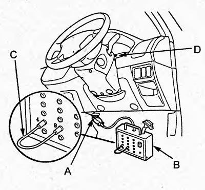
3. Connect the special tool (B) to the code erasing connector (A).
Caution: Do not use a jumper.
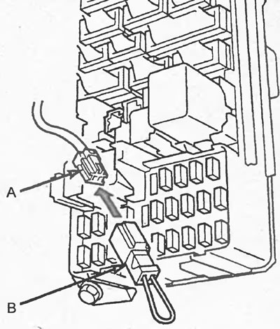
4. Turn the ignition switch to the "ON" position.
5. Disconnect the special tool from the code erasing connector within 4 seconds after the indicator goes out.
6. Make sure the "SRS" indicator lights up. Connect the special tool to the connector within 4 seconds after the indicator lights up.
7. Make sure the SRS indicator goes out. Disconnect the special tool from the code erasing connector within 4 seconds after the indicator goes out.
8. Check that the "SRS" indicator flashes twice and goes out.
If the indicator does not blink but lights up, repeat the authorization procedure. If the indicator blinks twice and continues to light up, go to step "9" and erase the error codes.
9. Turn the ignition switch to the "OFF" position and wait 10 seconds. Disconnect the special tool from the diagnostic connector or the connector for erasing codes.
10. Turn the ignition switch to the "ON" position. Make sure that the "SRS" indicator comes on for 6 seconds and goes out.
If the indicator does not light within 30 seconds, the front passenger position detection system unit has been authorized successfully.
Checking the current fault
Note: The check is performed if the diagnostics displays a current fault code.
1. Read the fault codes.
2. Clear fault codes.
3. Move the automatic transmission selector to position "P" or "N", start the engine and let it idle.
4. Check that the "SRS" indicator comes on for 6 seconds and goes out.
5. Wiggle the wires and connectors, perform a road test (acceleration, braking, turns). Turn the steering wheel all the way to the left and right and hold it in the extreme positions for 5-10 seconds.
If the malfunction recurs, the "SRS" indicator will light.
If the malfunction does not recur, the passive safety system is operational.
Based on materials from the website: HondaBook.ru