
Withdrawal
1. Disconnect the negative cable from the battery.
Attention! If the stereo system installed in the car is equipped with a security code, before disconnecting the battery, make sure that you have the correct combination to activate the audio system!
2. Remove the resonator, air intake sleeve and air cleaner cover (see chapter Power and exhaust systems).
3. Remove the electrical wiring and its mounting bracket from the starter (see chapter Engine electrical equipment).
4. Disconnect the ground bar from the transmission.
5. Disconnect the lockout control solenoid connector (see Checking and replacing the solenoid valves for blocking control).
6. Disconnect wiring from VSS (see part 5-speed manual gearbox this chapter)
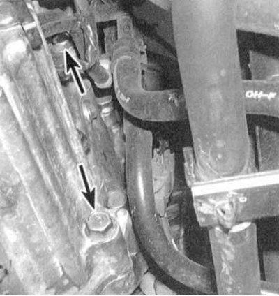
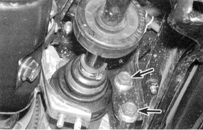
7. Turn out three top bolts of fastening of transmission to the engine (see accompanying illustration), as well as the bolt of the rear support of the power unit.
8. Jack up the car and put it on stands.
9. Drain the ATF from the transmission. When reinstalling the drain plug, be sure to replace the sealing washer on it.
10. Disconnect the lower suspension arms from the steering knuckles (see chapter Suspension and steering).
11. Release the drive shafts from the final drive assembly (see chapter Clutch and drive shafts). Wrap the inner CV joint assemblies in plastic bags to protect them from contamination.
12. Remove the right damper fork (see chapter Suspension and steering).
13. Remove drive shafts (see chapter Clutch and drive shafts).
14. Remove the crankcase protection.
15. Remove the cranked section of the exhaust system passing under the power unit (see chapter Power and exhaust systems).
16. Remove the shift cable dock cover, then remove the control lever and shift cable (no need to disconnect the cable from the lever).
17. Remove the stop support (see part 5-speed manual gearbox this chapter).
18. Disconnect the TV cable from the throttle position control lever (see Checking and adjusting the kick-down throttle cable (TV cable) - Integra models).
19. Disconnect the ATF cooling path hoses from the metal lines. Turn the hoses with the open ends up and plug them immediately to prevent fluid from escaping.
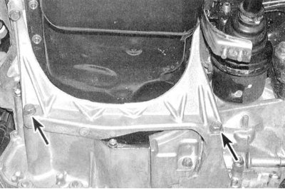
20. Remove the rib (A) stiffness of the power unit (see accompanying illustration).
21. Remove the encoder access cover (AT) /flywheel (CVT).
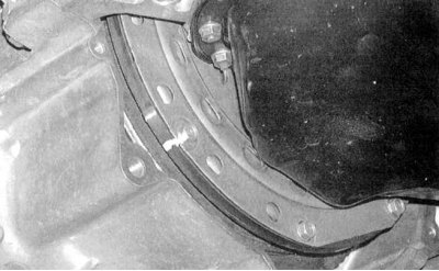
22. Mark the position of the rotary encoder (AT) /flywheel (CVT) in relation to the drive disk (see accompanying illustration) – when assembling, the components must be installed strictly in their original positions.
23. Loosen the rotation transducer/flywheel bolts to the drive plate one by one. To provide access to the next bolt, turn the crankshaft by the pulley.
24. Turn out a bolt of fastening of the distributor of ignition and connect lifting rigging to the engine.
25. Jack up the transmission (as special as possible), fixing it on the head of the latter with a safety chain. Raise the transmission by unloading its supports.
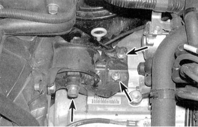
26. Remove the side support (see accompanying illustration).
27. Turn out the bottom bolt of fastening of transmission to the engine, and also bolts of a back support of the power unit (see accompanying illustration).
28. Pull the jack back, removing the transmission from the guide pins. Make sure that the rotation converter is disconnected from the drive disk. Secure the transducer in the transmission to prevent it from falling out during dismantling of the assembly. Lower the transmission and remove it from under the vehicle.
Note. It may be necessary to slightly lower the jack/eject the winch supporting the engine while lowering the transmission in order to free up more working space.
Installation
1. Car manufacturers (Honda) it is recommended to flush the ATF cooler and the lines of the cooling path with a solvent. Make sure no solvent remains in cooler lines/cavities after flushing is completed. It would be wise to finally flush the cooler with clean ATF to ensure the guarantee.
2. Install the starter (see chapter Engine electrical equipment).
3. Before installation, make sure that the rotation converter hub is properly engaged in the pump. Having fixed the transmission on the jack, bring it to its regular position (try not to tilt the assembly to prevent the transducer from falling out of it).
4. Achieve the correct alignment of the marks of the position of the transducer relative to the drive disk, applied during the dismantling process.
5. Make sure that the drive pins are in their sockets, then carefully slide the transmission onto them, making sure that the transducer is correctly engaged.
6. Screw in the lower bolt of fastening of transmission to the engine and the lower bolt of fastening of the engine to transmission. Tighten the bolts to the required torque.
Attention! Do not use bolts to tighten the transmission to the engine. If you cannot press the assembly, try to identify the cause and eliminate the interference.
7. Further installation is carried out in the reverse order of dismantling.
8. Fill the transmission with the required amount of ATF of the required grade (see chapter Current service). Do not be alarmed if you need to fill in liquids a little more than specified by the standards - the excess will be spent on filling the rotation converter, which is not emptied during the normal ATF change.
9. Start the engine, apply the parking brake and move the selector lever through all positions three times. Make sure the shift cable is working properly (see Replacing and adjusting the shift cable).
10. Check the setting of the ignition timing, if necessary, make the appropriate adjustment (see chapter Current service).
11. Warm up the engine to normal operating temperature (transmission in position "N" or "R"), then turn it off and check the ATF level.
12. Drive the vehicle, then check the power package for signs of fluid leaks.