
Withdrawal
1. Disconnect the negative cable from the battery.
Attention! If the stereo system installed in the car is equipped with a security code, before disconnecting the battery, make sure that you have the correct combination to activate the audio system!
2. Remove the air intake sleeve and air cleaner cover (see chapter Power and exhaust systems).
3. Remove the battery and its support tray (see chapter Engine electrical equipment). Disconnect the ground bar from the transmission case.
4. Disconnect the electrical wiring, remove the mounting bolts and remove the starter assembly (see chapter Engine electrical equipment).
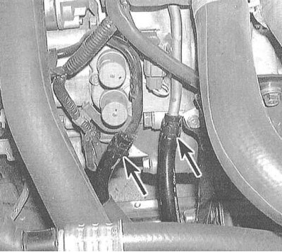
5. Disconnect wiring from VSS and transmission control solenoid valves (see Sections Adjustment and replacement of the transmission position sensor-switch and Check and replacement of electromagnetic valves of management of functioning of transmission).
6. Jack up the car and put it on stands. Remove the front wheels.
7. Hang the power unit from above using a winch or a beam laid over the edges of the hood.
8. On 4-cylinder models, remove the bolts securing the power unit support bracket to the transmission. On V6 models, give the nut securing the front support cushion of the unit to the bracket.
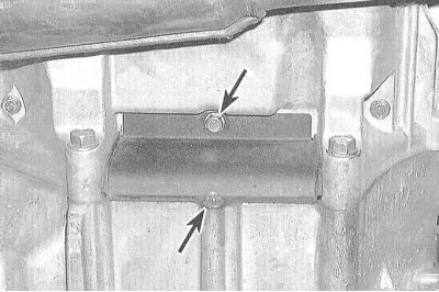
9. Remove the crankcase protection.
10. Drain the ATF from the transmission. When screwing the drain plug into place, do not forget to replace its sealing washer.
11. Disconnect the ATF cooling path hoses.
12. Disconnect the electrical wiring of the λ-probe (see chapter Engine management).
13. Remove the exhaust pipe (see chapter Power and exhaust systems).
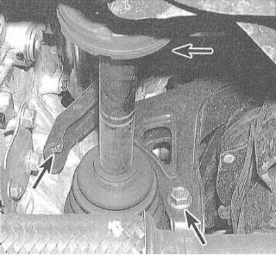
14. Release the damper forks from the suspension control arms (see chapter Suspension and steering).
15. Give the castellated nuts of the ball bearings and disconnect the lower levers from the steering knuckles (see chapter Suspension and steering).
16. Release the drive shafts from the final drive assembly (see chapter Clutch and drive shafts). Wrap the inner CV joint assemblies in plastic bags to protect them from contamination. Tie the drive shafts with wire to the suspension elements, not allowing them to hang with their entire weight on the outer CV joints. Remove intermediate shaft.
17. Turn out the bolts of the right and left push rods and separate the latter from the suspension control arms (see chapter Suspension and steering).
18. Mark the position of the subframe relative to the chassis and release the power steering hydraulic lines from the clamps on the subframe.
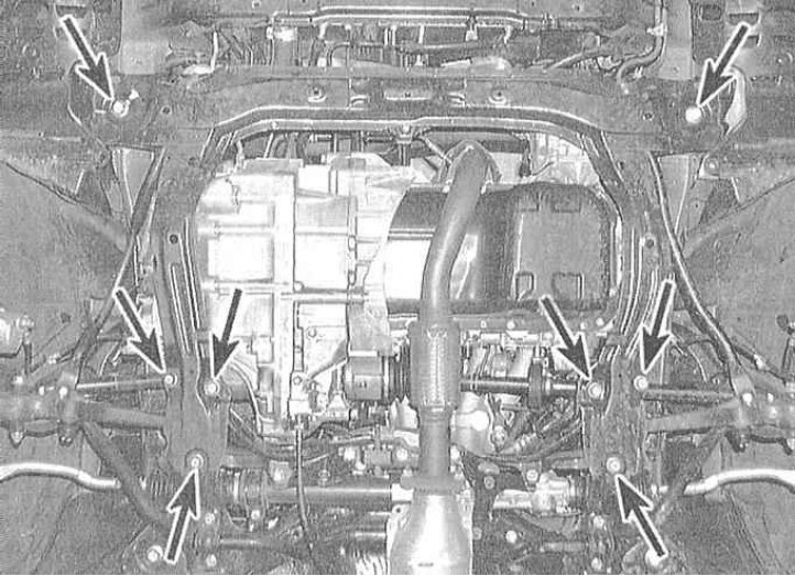
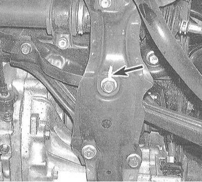
19. On V6 models, give the nuts securing the lower supports to the subframe. Remove the mounting bolts and remove the subframe assembly from under the car.
20. On V6 models, remove the power unit booster plate mounting bolts. On 4-cylinder models, remove the booster assembly.
21. Remove the shift cable holder (see Section Removal, installation and adjustment of a cable of a gear change).
22. Remove the shift cable (see Section Removal, installation and adjustment of a cable of a gear change).
23. Mark the position of the rotation converter relative to the drive disk - during assembly, the components must be installed strictly in their original positions in order to avoid imbalance.
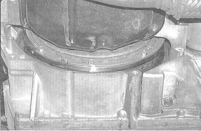 |  |
24. Loosen the bolts securing the rotation transducer to the drive disk one by one. To provide access to the next bolt, turn the crankshaft by the pulley.
25. Turn out two back bolts of fastening of a case of transmission to a wall of the engine.
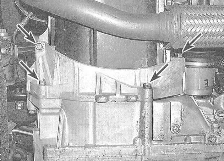
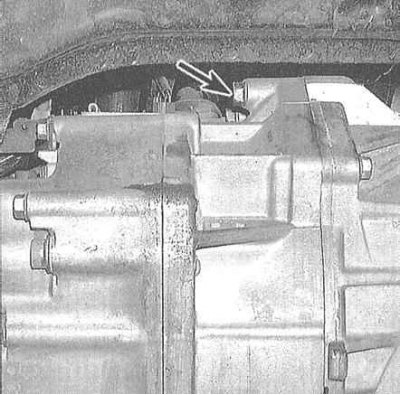
26. On 4-cylinder models, remove the power unit rear support bracket bolts.
27. On 4-cylinder models, remove the intake manifold mounting bracket (next to the powertrain rear support bracket).
28. Remove the power unit supports from the transmission (see chapter Engine). On V6 models, remove the front implement support bracket.
29. Jack up the transmission (as special as possible), fixing it on the head of the latter with a safety chain. Lift the assembly, completely unloading its supports.
30. Give nuts of an arm of a support and turn out the remained bolts of fastening of transmission to the engine.
31. Remove other chassis or suspension components that interfere with the dismantling of the transmission.
32. Pull the jack back, removing the transmission from the guide pins. Make sure that the rotation converter is disconnected from the drive disk. Secure the transducer in the transmission to prevent it from falling out during dismantling of the assembly. Lower the transmission and remove it from under the vehicle.
Note. It may be necessary to jack up the winch holding the engine slightly while lowering the transmission in order to free up more working space.
Installation
1. Car manufacturers (Honda) it is recommended to flush the ATF cooler and the lines of the cooling path with a solvent. Make sure no solvent remains in cooler lines/cavities after flushing is completed. It would be wise to finally flush the cooler with clean ATF to ensure the guarantee.
2. Before installation, make sure that the rotation converter hub is properly engaged in the pump.
3. Having fixed the transmission on the jack, bring it to its regular position (try not to tilt the assembly to prevent the transducer from falling out of it).
4. Achieve the correct alignment of the marks of the position of the transducer relative to the drive disk, applied during the dismantling process.
5. Check that the two drive pins are in their sockets, then carefully slide the transmission onto them, making sure the transducer is properly engaged.
6. Screw in four bolts of fastening of transmission to the engine and tighten them with the demanded effort.
Attention! Do not use bolts to tighten the transmission to the engine. If you cannot press the assembly, try to identify the cause and eliminate the interference.
7. Further installation is carried out in the reverse order to the dismantling of the components. When installing the subframe, make sure that the landing marks applied during the dismantling process are aligned correctly. Tighten the subframe fasteners to the required torque (see also Chapter Specifications Suspension and steering). The required tightening forces for the fasteners of the power unit supports are given in the Specifications for the Chapter Engine.
8. Fill the transmission with the required amount of ATF of the required grade (see chapter Settings and ongoing maintenance). Do not be alarmed if you need to fill in fluids a little more than specified by the standards - the excess will be spent on filling the rotation converter, which is not emptied during the normal ATF change.
9. Start the engine, apply the parking brake and move the selector lever through all positions three times. Make sure the shift cable is working properly (see Section Removal and installation of the switching lever (selector) gear).
10. Warm up the engine to normal operating temperature (transmission in position "N" or "R"), then turn it off and check the ATF level.
11. Drive the vehicle, then check the power package for signs of fluid leaks.
12. In the event of vibration, loosen and re-tighten with the required force the fasteners of the power unit supports (see chapter Engine).
13. Perform front wheel alignment.