
Attention! The vehicles covered in this manual are equipped with airbags (SRS). When performing any work near the shock sensors, steering column or instrument panel, turn off the SRS (see wiring diagrams at the end of the Chapter Onboard electrical equipment).
General information
All AT-equipped models have a locking system to prevent unintentional gear changes. The locking system consists of two subsystems: the shift lock system and the key lock system.
Key lock system
The system prevents the key from being removed from the ignition switch until the selector lever is moved to the "R". When a key is entered into a lock in any other "R" position of the lever, the electromagnetic actuator is activated, making it impossible to remove the key. To remove the key, move the lever to the desired ("R") position.
Shift lock system
The system prevents the selector lever from being moved out of position "R" into the provisions "R" or "D" without depressing the foot brake pedal. The lock is also activated when the brake and accelerator pedals are depressed at the same time. In the event of a system failure, the lever can be unlocked by inserting a key into a special slot near the lever assembly.
Examination
The following checks of the electromagnetic actuators of both interlocks can be done on their own by an amateur mechanic at home. A more detailed diagnosis of the system should be performed in a car service workshop.
Electromagnetic ignition key lock actuator
1. Remove the lower section of the instrument panel trim and knee brace (see chapter Body).
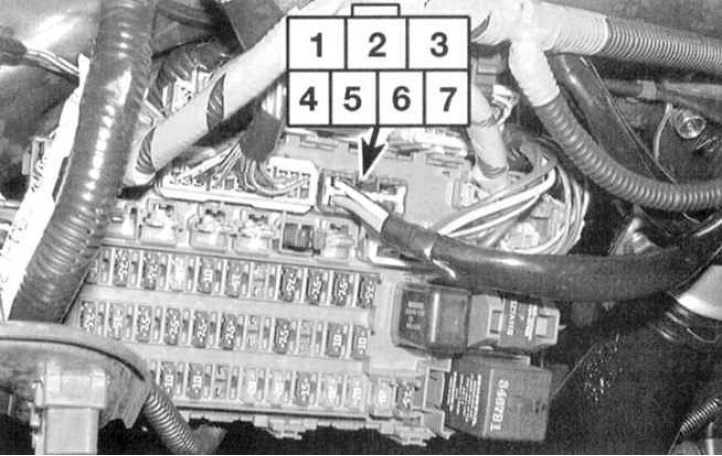
2. Disconnect the 7-track connector of the main wiring harness (see accompanying illustration).
3. Check up a socket on existence of conductivity between plugs in various provisions of the switch of ignition. When the key is pressed into the lock, conduction must take place between terminals 5, 6 and 7. When the key is released, between terminals 5 and 6 (about 15÷20 Ohm in the latter case).
4. Make sure that key removal is not possible when battery voltage is applied to terminals 5 and 7.
5. If the key is not removed, then the locking system is functioning properly, otherwise it is necessary to replace the ignition lock assembly (blockers are not issued individually).
Solenoid shift lock actuator
1. Remove the console (see chapter Body).
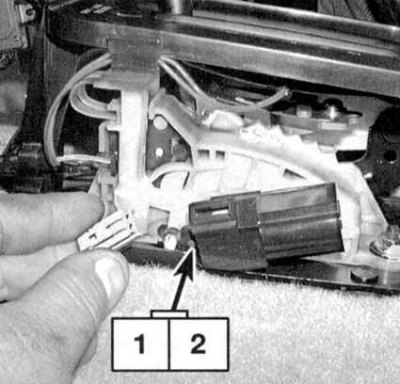
2. Disconnect the shift lock solenoid 2-pin connector (see accompanying illustration).
3. Using two jumper wires, momentarily connect the battery to the connector terminals (positive pole to terminal 1, negative to terminal 2) and by ear make sure that the blocker is working properly.
Attention! Reversing the polarity of the battery connection is fraught with failure of the diode inside the electromagnetic assembly.
- a) If there is no click, replace the solenoid assembly;
- b) If the device works normally, but problems with blocking remain, you should try to make adjustments (see below).
4. With the electromagnetic device turned on, measure the gap between the locking lever and the notch of the locking pin (see below).
5. With the electromagnetic device turned off, make sure that the locking pin is locked by the locking lever. If the finger is not blocked, adjust the electromagnetic device (see below).
Replacement and adjustment of the electromagnetic actuator
Note. The procedure below applies to the shift lock only. Information on replacing the ignition key lock solenoid actuator is given in the Section on replacing the ignition lock cylinder (see chapter Onboard electrical equipment).
1. Remove the locking sleeve and solenoid pin.
2. Give self-locking nuts and remove the electromagnetic device of blocking of a gear change.
Note. Nuts must be replaced without fail.
3. Installation is carried out in the reverse order. Do not fully tighten the new nuts until after you have adjusted the solenoid (see below).
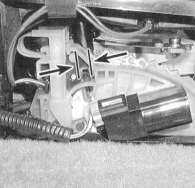
4. To adjust the shift lock solenoid actuator, apply power to it and measure the gap between the lock lever and the notch of the lock pin (see accompanying illustration). Compare measurement results with requirements Specifications. If necessary, adjust the gap by adjusting the position of the electromagnetic device, then finally tighten the self-locking nuts of its fastening with the required force.
Note. Don't forget to replace the self-locking nuts.
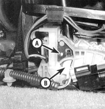
5. Make sure that when the electromagnetic device is turned off, the locking pin is fixed by the locking lever (see accompanying illustration). If the finger is not blocked, repeat the adjustment of the position of the electromagnetic device.