
Note:
- The GVT type is stamped on an aluminum plate affixed to the bulkhead of the engine compartment, in line "TRANS/AXLE".
- Fluid change procedure c. variator, see chapter "Maintenance and general inspection and adjustment procedures".
General information
The variator consists of a continuously variable transmission (two compound pulleys and a metal belt), planetary gear (for reversing), intermediate gear, main gear and elements of the control system.
The mechanical part of the variator consists of four parallel shafts (input shaft, CVT drive pulley shaft, CVT driven pulley shaft and final drive shaft). The input shaft is directly connected to the engine flywheel. The input shaft is connected to the drive pulley shaft through a planetary gear. A starting clutch is also installed on the shaft of the driven pulley, which ensures the start of the car's movement and the drive gear of the intermediate gear. The driven gear of the intermediate gear is rigidly connected to the drive gear of the main gear.
To control the operation of the planetary gear set of the variator, a forward clutch and a reverse brake are used.
Electrical part of the control system
The electrical part of the variator control system consists of three parts:
- A) Sensors that determine the parameters of the state of the car, and transmit this data to the electronic control unit.
- b) The control unit, which determines the gear ratio of the continuously variable transmission, changes the direction of the vehicle depending on the selected range.
- V) The executive part, which consists of solenoid valves.
The control unit with the help of electromagnetic valves changes the distance between the cheeks of the pulleys, thus changing the gear ratio.
Variable speed solenoid valve changes pressure (DRC), supplied to the control valve of the drive pulley.
Pulley pressure control solenoid valve changes pressure (DNC), supplied to the control valve of the driven pulley.
Starting clutch control solenoid valve changes the pressure supplied to the starting clutch (SQ), which varies depending on the degree of opening of the throttle valve.
Driven pulley control solenoid valve changes pressure (DR), connected to the driven pulley.
Driven pulley control solenoid valve changes pressure (DN), connected to the driven pulley.
Manual gear change mode
On some modifications, there is a mode for manually changing the gear ratio of the variator.
In this mode, there are seven fixed positions of the CVT pulleys, corresponding to the gears of a conventional gearbox. Seven "gear" are changed by the driver using the gear ratio up and down switches on the steering wheel. The selected gear ratio number is displayed on the instrument cluster (range from "1" before "2").
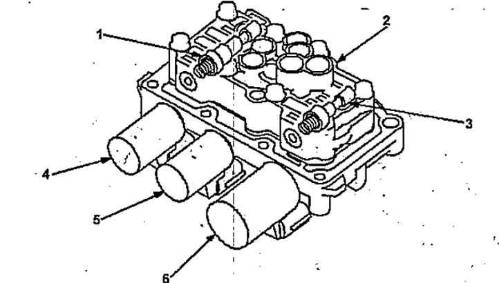
Solenoid valves.
1 - solenoid valve for driving pulley control,
2 - valve bolt,
3 - solenoid valve for controlling the driven pulley,
4 - solenoid valve for measuring speed,
5 - solenoid valve for pulley pressure control,
6 - solenoid valve for control of the starting clutch.
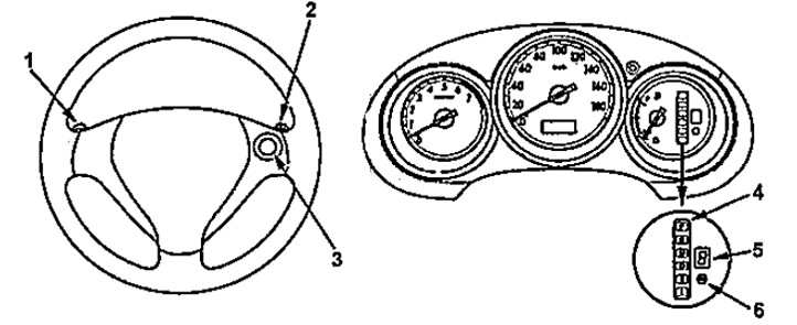
1 - upshift switch in manual shift mode,
2 - downshift switch in manual shift mode,
3 - manual switching mode switch,
4 - position indicators of the variator selector,
5 - indicator of the selected gear ratio,
6 - indicator for enabling the manual switching mode.