
Examination
Attention! The vehicles covered in this manual are equipped with airbags (SRS). When performing any work near the shock sensors, steering column or instrument panel, turn off the SRS (see wiring diagrams at the end of the Chapter Onboard electrical equipment).
1. Remove the console (see chapter Body).
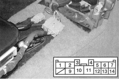
2a. Disconnect the 14-pin selector lever position switch electrical connector (see accompanying illustrations): Civic models.
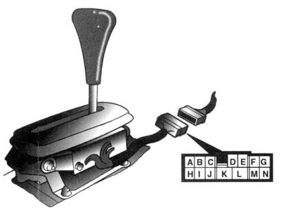
2b. Integra models.
3. Check the sensor-switch for compliance of the states of the sensor-switch with conductivity maps (see accompanying illustrations). Move the selector lever alternately to each of the positions without touching the push button. Remember that the amount of free play of the lever in each of the positions is about 2 mm. If the test results are negative, adjust the sensor-switch (see below).
Conductivity map of the selector lever position sensor-switch (Civic models)
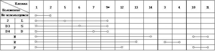
1-7 - Lever position switch
3—4 — the Sensor-switch of lights of a backing
10—11 - Start enable switch
* - Tempostat
Conductivity map of the selector lever position sensor-switch (models Integra models without tempostat)
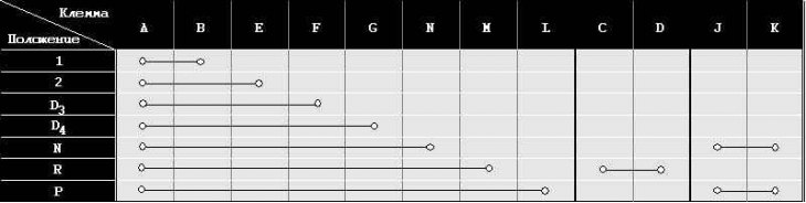
A—L - Lever position switch (models without tempostat)
C—D - Sensor-switch of reversing lights
J—K - Start enable switch
Adjustment
1. Move the selector lever to position "R" and loosen the sensor-switch fastening nuts (see illustration below).
2. Move the lever towards the position "D" until there is continuity between terminals 2 and 14 (Civic) /A and L (Integra) switch sensor connector. Conductivity must be maintained within the free play of the lever (about 2 mm).
3. Carry out the check described in paragraph 3 (Examination) higher. Make sure the engine starts in position "N" lever.
4. If the requirements of the conductivity map still remain unfulfilled, check the condition of the retainer and the selector lever bracket. If no damage can be found, replace the sensor-switch.
Replacement
1. Remove the console (see chapter Body).
2. Disconnect the 14-pin sensor-switch connector (see illustrations above).
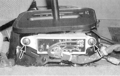
3. Give two fixing nuts (see accompanying illustration), remove washers. Remove the sensor switch.
4. Move the slider of the new sensor-switch to the neutral position (position "N").
5. Move the selector lever to position "N" and install a new sensor-switch.
6. Put on the washers and fix the sensor-switch with nuts.
7. Check the sensor-switch according to the instructions given in paragraph 3 (Examination). Make sure the engine starts in position "N" selector lever.
8. Connect an electric socket of the gauge switch. Secure the wiring harness in all provided clamps.
9. Replace console (see chapter Body).